Table of Contents
Advertisement
For trailers with 2-8 electric brakes and vehicles with 12 volt negative ground systems only.
• Before beginning installation, read and become familiar with these instructions.
• Leave these instructions in tow vehicle for future reference.
• IMPROPER INSTALLATION AND OPERATION COULD CAUSE PERSONAL INJURY AND/OR
EQUIPMENT AND PROPERTY DAMAGE.
!
!
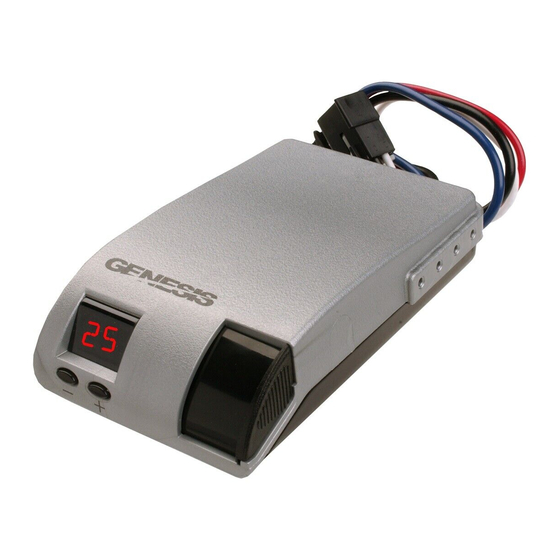
Electronic Brake Controller
Hayes Brake Controller Company - P/N 81790
Installation MANUAL
READ AND SAVE THESE INSTRUCTIONS
WARNING:
Indicates a potentially hazardous situation that,
if not avoided, could result in death or serious, personal injury.
CAUTION:
Indicates a potentially hazardous situation that,
if not avoided, could result in damage to product or property.
TIP:
Contains helpful information to facilitate installation.
GENESIS
Advertisement
Table of Contents
Troubleshooting

Related Manuals for Hayes Genesis 81790


Summary of Contents for Hayes Genesis 81790
- Page 1 GENESIS Electronic Brake Controller Hayes Brake Controller Company - P/N 81790 INSTALLATION MANUAL For trailers with 2-8 electric brakes and vehicles with 12 volt negative ground systems only. READ AND SAVE THESE INSTRUCTIONS • Before beginning installation, read and become familiar with these instructions.
- Page 2 Installation CAUTION: • In the automatic mode and minimum power setting of 5 or 10, the trailer brakes are applied only when the sensor detects deceleration. • With the vehicle at rest and the brake pedal depressed, there should be no or slight output to the trailer brakes (when minimum power is set to 5 or 10).
- Page 3 Controller Mounting and Installation Mounting Mounting Tinnerman Nut Bracket Bracket Self Tapping Screws Pan Head Machine Screw Figure 3 – Attachment of Mounting Bracket Controller and Mounting Bracket • The bracket provided is to be used for mounting the controller to the tow vehicle. •...
- Page 4 Read all wiring instructions prior to making electrical connections to the tow vehicle. WARNING: To reduce the risk of injury or damage to property: • Always connect the white wire first and the black wire second. • All four controller wires must be connected properly for the controller to operate correctly.
- Page 5 ” Wiring Harnesses are available for all Hayes Brake Controllers fitted with a connector on the wire leads, making connection a snap. Harnesses are available through all dealer resources. Ask specifically for the Hayes Brake Controller Company (HBC) brand harnesses to match your controller.
- Page 6 Special Conditions For tow vehicles equipped with factory trailer towing package: • Refer to your vehicle’s owner’s manual or other information provided by the manufacturer in determining the correct connection points for the controller. • See Appendix section for partial list of manufacturer wiring harness to controller conversions. For vehicles without a trailer-towing package: refer to the wiring diagram in Figure 4.
- Page 7 Appendix OEM TOW VEHICLE WIRING CONVERSIONS CHRYSLER (THROUGH 2002) CONTROLLER FUNCTION CHRYSLER (NEW) RED W/BLACK TRACE BLACK +12 VOLT SUPPLY WHITE WITH RED TRACE WHITE W/TAN TRACE STOPLIGHT BLUE WITH WHITE TRACE BLUE BLUE TRAILER BRAKES BLUE BLACK WHITE GROUND GREEN W/BLACK TRACE FORD (THROUGH 2002) CONTROLLER...
- Page 8 GENESIS Electronic Brake Controller Hayes Brake Controller Company - P/N 81790 OPERATION MANUAL For trailers with 2-8 electric brakes and vehicles with 12 volt negative ground systems only. READ AND SAVE THESE INSTRUCTIONS • Before beginning installation, read and become familiar with these instructions.
- Page 9 Automatic Operation During braking, the Genesis senses deceleration of the tow vehicle. An internal sensor measures the amount of deceleration and sends a proportional amount of power to the trailer brakes. The maximum braking supplied depends on the set up of the controller. The digital display will indicate the amount of power being sent to the trailer brakes.
- Page 10 Definitions of Options Brake Controller Item # 81790 Quick Reference Option Available Selections Change procedure P : % of available power being • Press “+” button until the display flashes and release Display Mode sent to trailer brakes (PH for •...
- Page 11 WARNING: • Improper adjustment of the controller could result in loss of trailer brakes, aggressive, grabby, pulsating, or delayed trailer brakes. • Power adjustments may be required based upon speed, trailer load, and road conditions. • Maximum trailer braking occurs just prior to lockup of the trailer wheels. •...
- Page 12 C. After a few hours of being inactive (with a trailer connected), the display will go blank. While the display is blank, very little power will be used by the Genesis. Minimum Power: (for Manual and Automatic operation) CAUTION: • In the automatic mode and minimum power setting of 5 or 10, the trailer brakes are applied only when the sensor detects deceleration.
- Page 13 Maximum Power (for Automatic braking only): The controller is factory pre-set to 50%. When the controller senses maximum deceleration, the most power that the controller will send to the trailer brakes will be 50%. Changing Maximum Power for Automatic operation only (Manual operation is not affected) Note: To change the maximum power level, the controller must be in “normal”...
- Page 14 Troubleshooting using the manual slide To verify the brake controller is properly wired, follow these steps: A. Disconnect the tow vehicle/trailer electrical connector. Set the display mode to PH. Move the manual slide lever (Figure 1) to the left. The displayed value should increase and the tow vehicle stop lamps must illuminate.
- Page 15 TIP: • Warm trailer brakes tend to be more responsive than cold brakes. There are two methods of adjusting the output and responsiveness of the Genesis Brake Controller. They are listed here in the order in which they should be modified: 1.
- Page 16 Open Circuit: The display will flash “OC”. This is an indication that there is no trailer connected to the tow vehicle. Flashing “OC” will display for a few minutes or until a trailer is connected to the tow vehicle. Connection to electric over hydraulic trailer brakes can also cause the display to flash “OC”. The display will go blank when no load is detected for several minutes.
- Page 17 Troubleshooting Symptom Possible Cause Remedy Trailer Brakes “Lock Up” Maximum power set too high Reduce maximum power setting Minimum power set too high Reduce minimum power setting Low output to trailer Maximum power set too low Increase maximum power setting brakes Minimum power set too low Increase minimum power setting...
- Page 18 • Faulty wiring • Malfunctioning or disconnected break-away switch Controller displays flashing No trailer connected Flashing will stop in a few minutes “OC” Trailer with Electric over Change Display mode to PH or EH Note: If the display mode Hydraulic actuator attached Note: These two modes do not is set to PH or EH, the check for a trailer connection.
Need help?
Do you have a question about the Genesis 81790 and is the answer not in the manual?
Questions and answers
I have a 81790 controller that is flashing "8.8." I **** troubleshooting the brake lights staying on all the time on a 85 F250 and **** getting close to thinking the controller might be kaput. No other display can be had by mashing the buttons. Help!!
The "8.8." display on a Hayes Genesis 81790 controller indicates that the digital display is functioning and all display segments are working. It typically appears during power-up as a segment check.
This answer is automatically generated