Table of Contents
Advertisement
Available languages
Available languages
Quick Links
INSTALLATION INSTRUCTIONS
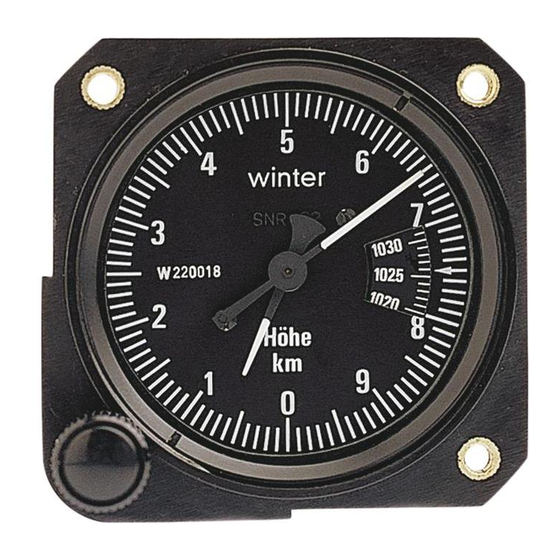
The mounting dimensions of the altimeter correspond to the so-called small standard. The
diameter of the hole in the instrument panel is 57 mm, the hole circle diameter on the mounting
flange is 67 mm. M 4 countersunk screws are used for fastening. The instrument panel should be
flat and fixing holes should be accurately located for stressfree mounting of the instrument. The
instrument panel should be well sprung.
The altimeter must be connected to the static pressure. Static pressure is tapped either from the
second connection of the pitot tube or by static pressure sensor attached to the fuselage sides.
The pressure tapping point should be selected so that no errors are produced from air flow around
the aircraft fuselage.
Hose leads should be as short as possible and must not be twisted or contain sharp bends.
Kinking of hoses should be avoided in all cases. Hoses and connections must be absolutely leak-
tight. The instruments must be protected from water penetration. If the hoses from the pressure
tapping points cannot be run upwards, a water trap (waterbag) should be fitted at the lowest point.
Before putting into service, a test must be carried out for leak-tightness. If the aircraft manufacturer
has not given any special instructions for this, our standard instruction for leak-tightness testing,
January 1978 edition, can be used.
MAINTENANCE INSTRUCTIONS
Leak testing should be carried out at least every 2 years. Otherwise, the instrument does not
require any maintenance.
RETESTING AND REPAIR
The service condition and accuracy of measurement of the altimeter is normally retained over a
long period. For obvious malfunction the unit should be subjected to an investigation at the
manufacturer or a suitable aircraft engineering company. It should be packed to protect it from
impacts, and the connections should be sealed. Under no circumstances should you interfere with
the measuring mechanism of the altimeter. We recommend that altimeters are subjected to
periodic retesting after 5 years.
ACCOMPANYING DOCUMENT:
New instrument:
1) Test certificate EASA FORM ONE
2) Installation and maintenance instructions
Used instrument:
1) Test certificate EASA FORM ONE
ATTENTION
This issue replace all previous editions.
Gebr. Winter GmbH & Co. KG
Hauptstraße 25 · D-72417 Jungingen
Telefon +49 (0) 74 77 2 62 + 15 12 63
Telefax +49 (0) 74 77 10 31
e-mail: info@winter-instruments.de
Internet: www.winter-instruments.de
LBA-Anerkennung:
mounting dimensions:
mounting dimensions:
Herstellungsbetrieb gemäß EASA Ref. DE.21G.0115
Instandhaltungsbetrieb gemäß EASA Ref. DE.145.0305
EINBAU- UND WARTUNGSANWEISUNG FÜR DIE HÖHENMESSER
4 FGH 20 und 4 FGH 40
Ausgabe: September 2014
INSTALLATION AND MAINTENANCE INSTRUCTIONS FOR ALTIMETERS
4 FGH 20 and 4 FGH 40
Issue: September 2014
4 FGH 20 S Nr. 4220
4 FGH 40, S Nr. 4550
Advertisement
Table of Contents

Related Manuals for Winter 4 FGH 40


Summary of Contents for Winter 4 FGH 40
- Page 1 4 FGH 20 und 4 FGH 40 The pressure tapping point should be selected so that no errors are produced from air flow around Ausgabe: September 2014 the aircraft fuselage.
- Page 2 TECHNICAL DESCRIPTION TECHNISCHE BESCHREIBUNG EINBAUVORSCHRIFTEN Verwendungszweck: Zweizeiger-Gerät 4 FGH 20 bzw. Dreizeigergerät 4 FGH 40 zur Mes- Purpose: Twin-needle instrument type 4 FGH 20 or three-needle instru- Die Einbaumaße des Höhenmessers entsprechen der so genannten kleinen Norm. Der sung der relativen und absoluten Flughöhe von Segelflugzeugen, ment type 4 FGH 40 for measurement of relative and absolute Durchmesser des Ausbruchs im Instrumentenbrett beträgt 57 mm, der Lochkreisdurchmesser...
Need help?
Do you have a question about the 4 FGH 40 and is the answer not in the manual?
Questions and answers