
Related Manuals for Neilsen CT4539

Summary of Contents for Neilsen CT4539
- Page 1 CT4539 ORIGINAL INSTRUCTIONS Cannon Tools Limited Address: 20 Station Road, Rowley Regis, West Midlands, B65 0JU.U.K Read and understand the user and safety instructions before you use the generator.
-
Page 3: Ec Declaration Of Conformity
Declare that the design and construction of the following machine, in the form supplied by us, comply with the requirements of the appropriate EC directives. Product description: GASOLINE GENERATOR , WELDER & COMPRESSOR Model: CT4539 Type: AC output / AC tool fulfills all the relevant provisions of Directives... - Page 4 We want to thank you for your purchase of our state of the art new CT4539 .This manual will tell you how to use and maintain the new CT4539 ,Please read the manual carefully before operating the machine.Operating the machine in the best conditions will increase the lifetime of the unit.
- Page 6 GRAPHIC SYMBOLS AND INDICATIONS duty cycle The ratio of given duration time/the full-cycle time Note1: This ratio shall be within 0~1, and can be indicated by percentage. Note2: In this standard, the full-cycle time is 10min. For example, if the duty cycle is 60%, the load-applying time shall be 6min and the following no-load time shall be 4min.
- Page 7 1 .Safety Instruction Please read the manual before operation,failure to comply with the manual could lead to danger of operato r,others and the machine. - Before use, the generating set and its electrical equipment (including lines and plug connections) should be checked to ensure that they are not defective.
- Page 8 Protection. Do not let your body touch the ground and the electrode at that same time. 1.4 Welding fumes and gasses can cause serious harm to operator and all other by standards. Please keep your head away from a place you could possibly breathe in fumes and make sure to use the machine in a well ventilated area.
- Page 9 1.10. The engine operates on gasoline. It is important to keep in mind this unit can not be run indoors. Carbon Monoxide has no odor and can be fatal in a short period of time. 1.11. Gasoline is highly flammable and is capable of causing a large explosion.
- Page 11 2. General points of safety for Welding function During the welding process, it may cause damage to you and others, please do well the protection. For the details, please refer to the safety protection guide to the operators that accord with the manufacturer accident prevention requirements. Electric shock—it may cause death! In accordance with the application standard, install the grounding device well.
- Page 12 completed. Protect the environment from welding splatter. Remove flammable materials, such as flammable fluids, from the welding vicinity and supply the welding site with adequate fire fighting equipment. In special welding jobs, be prepared for hazards such as fire or explosion when welding container type work pieces.
- Page 13 on foot or lay), it must avoid directly contacting the current-carrying part on equipment with body. Don’t use the machine in the event the operating environmental space is very narrow and small which make the operator unable to step aside the current-carrying conductor. Don’t use the machine in humid environment, where the operators easy to sweat which make them in great electric shock risks Don’t conduct the welding in the dust area or under the environment of corrosive gas.
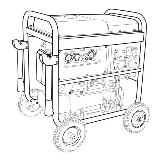
- Page 15 3.Structure Note: Do not attempt to modify the control panel in any way, This will void your warranty and could present the potential for equipment failure and personal injury. 6. Main Power Breaker 1. Engine Ignition Switch 7. 230VAC Output 2.
- Page 16 1. Engine Cover Plate 2. Fuel Tank 3. Fuel Petcock 4. Engine Pull-Start Assembly 5. Engine Chocke Lever 6. Air Filter Assembly 7. Water Drain Valve 8. Muffler Assembly 9. Frame 10. Raise shaft A intended for chain for crane lift 11.
-
Page 17: Pressure Gauge
2. Oil Fill Dipstick 1. Engine Oil Drain Plug 3. Air Pressure Relay 4. A/C Switch 5. Safety Valve 1. Pressure Gauge 2. Air Pressure Regulator 3. Air Outlet Connectors 4. Pressure Gauge 5. Air Tank 6. Air Hose 7. Air Valve... -
Page 18: Engine Oil Recommendation
4.4.2 Insert dipstick and then remove to check exact level of the oil. 4.5Engine oil recommendation 4.5.1 Oil is a major factor for overall performance of the CT4539. Please use 4 stroke oil that exceeds the standards for API service classification SE. - Page 19 Always check the API SERVICE label on the oil container to be sure it includes the letters SE. 4.5.2 Check and change the oil in your machine regularly. This will avoid all problems related to the oil being too low, too high, dirty or thick.
- Page 20 Use a strainer when adding fuel and make sure to always leave enough room at the top for fuel inflation to occur.Make sure you securely twist the fuel cap before operating the CT4539 . Do not use used,polluted or mixed fuel in the machine. 4.8 Check air filter.
- Page 21 5. Starting 5.1 Start the fuel valve The fuel valve is between fuel tank and the carburetor. When running the unit. the fuel valve is “on”. when stop the unit, the fuel valve turn to “off”. 5.2 Try to drain all fuel and turn the fuel petcock to the off position when the unit will sit for a long period of time without use.
-
Page 22: Operation
5.2.2 Recoil start: Make sure the unit to the unit is in the “on” position. Pull the re-cooil handle slightly until you feel resistance and then pull handle immediatel y. If failed, repeat uniil the unit has started. Gentle let the cord back down to avoid damaging the pull cord. -
Page 23: Special Warning
6.6 Welding rods and welding leads chart: For your reference below these are the rods and cables we see the best performance in the CT4539. 6~12 Above 13 Work piece thickness (mm) 3.2~4.0... - Page 24 empty compressor tank of all remaining air. If welding please remove rod connections. Let the unit run for 2-3 minutes, then turn the key on the control panel to the “off” position.. 7.2 If the unit must be transported a long distance. Make sure you stop the unit and remove any connections.
- Page 25 8.1.2 Make sure the oil is drained completely. Then tighten the bolt and replace the seal. To purchase a new seal please contact NEILSEN CT4539 Industrial. 8.1.3 Fill the unit with oil into the crankcase to the recommended level on the oil dipstick plug. Once you have...
- Page 26 4. Squeezing 1. Soak 8.3 Spark Plug Maintenance In order to keep your new CT4539 running at peak performance, the spark plug must be adusted to get rid the unit of any carbon laydown. Using the wrong spark plug will damae the engine. Make sure to contacting a NEILSEN CT4539 service technician before changing the spark plug.
- Page 27 on the spark plug. 8.3.1 After letting the unit cool down clean a dirty spark plug by first, removing the cap on the plug. Then you must remove the spark plug with the spark plug remover tool that came in the toolbox of your unit.
-
Page 28: Battery Maintenance
It is important to avoid any damage that the spark plug is tightened to the correct specifications. If you have any questions contact a NEILSEN CT4539 service technician for any information. 8.3.5 Install the spark plug cap. - Page 29 8.5.3 You must never let fuel sit or be stored for more than 30 days in your CT4539. 8.6 Taking off fuel tank and carburetor Fuel is highly combustible and explosive. It is important to remember when handing fuel you can easily be burned or hurt.
- Page 30 8.6.1 Put a gasoline container below the carburetor and use a funnel to protect against over spilling. 8.6.2 Loosen carburetor discharge bolt. Discharge any remaining fuel in the carburetor. 8.6.3 After discharging of all fuel into a container re tighten the discharde bolt.
- Page 31 9.SPECIAL SAFETY POINS FOR COMPRESSOR ATTENTION: When using the NEILSEN CT4539 Triad 3 in 1 and you hear unfamiliar noises coming from the unit it is important to stop the machine immediately and contact NEILSEN Industrial immediately.
- Page 32 9.1 GENERAL POINTS OF SAFETY FOR COMPRESSOR. 9.1.1 NEVER TOUCH MOVING PARTS Never place your hands, fingers or other body parts near the compressor’s moving parts. 9.1.2 NEVER OPERATE WITHOUT ALL GUARDS IN PLACE Never operate this compressor without all guards or safety features in place and in proper working order.
- Page 33 9.1.12 STAY ALERT Watch what you are doing. Use common sense. Do not operate compressor when you are tired. Compressor should never be used if you are under the influence of alcohol, drugs or medication that makes you drowsy. 9.1.13 CHECK DAMAGED PARTS AND AIR LEAK Before further use of the compressor, a guard or other part should be carefully checked to determine that it will operate properly and perform its intended function.
- Page 34 24 DO NOT DIRECT AIR STREAM AT BODY 9.1. Risk of injury, do not direct air stream at persons or animals. 25 DRAIN TANK 9.1. Drain tank daily or after 4 hours of use. Open drain fitting and tilt compressor to empty accumulated water.
-
Page 35: Troubleshooting
9.3.2 MAINTENANCE Before attempting any maintenance jobs on the compressor, make sure of the following: -Master power switch in position “OFF”. -Pressure switch and the control unit switch all off, in position “OFF”. -No pressure in the tank. Every 50 hours of duty: we advise you to dismantle the suction filter and clean the filtering element by blowing compressed air on it . - Page 36 9.4.3 Compressor turns but does not load Coaxial compressors : -This may be due to failure of the valves (C1-C2) or of a seal (B1-B2): replace the damaged part. Pulley drive compressors : -This may be due to failure of the valves F1 and F2 or of D2: replace the damaged part. -Check if there is too much condensate water inside the tank.
- Page 37 10.Common fault and processing methods Warning: when need any repair or replacement, contact your nearest service center, and ask the professional person to do any repair or replacement with the parts provided by the service center. fault failure process fault cause phenomenon charge battery( only for electric 1.
- Page 38 Working pressure high Reduce working pressure Not use correct lubricating oil Reference this manual and use Ambient high temperature or poor compressor correct compressor oil part ventilation Shift to good ventilation place overheat compressor valve block air Repair valve block or replace temperature leakage or damage compressor...
-
Page 39: Schematic Diagram
11. Schematic diagram... - Page 40 CANNON TOOLS LTD Add: 20 station road, Rowley Regis, west midlands,B65 0JU.U.K. Made in China...
Need help?
Do you have a question about the CT4539 and is the answer not in the manual?
Questions and answers