
Related Manuals for National Flooring Equipment 3395

Summary of Contents for National Flooring Equipment 3395
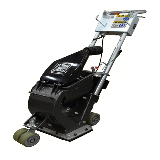
- Page 1 3395 SHOT BLASTER SERVICE MANUAL Read Manual Before Servicing Machine 402966 Rev F...
-
Page 3: Table Of Contents
Table of Contents Table of Contents ................................3 Specifications ................................4 Safety ....................................5 Maintenance Schedule ..............................7 Maintenance and Inspection ..........................7 Troubleshooting Guide ..............................8 General Errors ............................... 8 Electrical Errors ..............................9 Maintenance ................................. 10 Changing the Blast Wheel ........................... 10 Changing the Liners ............................. -
Page 4: Specifications
Up to 430 ft (45.4 kg) (1.12 Kw) Machine Variants Region Serial Number Input Power Max. Amps Body Panels 3395-10XXXX 120V / 60 Hz Silver Vein Domestic 3395-12XXXX 120V / 60 Hz Green 3395-23XXXX 120V / 60 Hz Silver Vein... -
Page 5: Safety
Read the manual carefully to learn equipment applications and limitations, as well as potential hazards associated with this type of equipment. Keep manual near machine at all times. If your manual is lost or damaged, contact National Flooring Equipment (NFE) for a replacement. Personal Maintenance &... - Page 6 Safety Safety Safety SHOT BLASTER SAFETY GUIDELINES Before use, anyone operating this equipment must read and understand these safety instructions. Dust Collection Shot Blasting Beware of hidden obtrusions. Turn off machine before working with dust collector. Watch out for hidden dangers and protrusions in flooring. Do not Do not switch off or remove the dust collector while the machine is use on largely uneven surfaces.
-
Page 7: Maintenance Schedule
Maintenance Schedule MAINTENANCE AND INSPECTION Safety and service life of the machine depend on proper maintenance. The following table shows recommendations about time, inspection, and maintenance for the normal use of the machine. The time indications are based on uninterrupted operation. When the indicated number of working hours is not achieved during the corresponding period, the period can be extended. -
Page 8: Troubleshooting Guide
Troubleshooting Guide GENERAL ERRORS Problem Cause Solution Unusual vibrations. Uneven wear of the blast wheel. Replace blast wheel set. Unbalance due to broken parts or blades. Check separator and all other sections of the machine. Remove all broken parts. Wheel hub worn out. Replace wheel hub. -
Page 9: Electrical Errors
Troubleshooting Guide ELECTRICAL ERRORS Problem Cause Solution Motor does not start up. Emergency stop is locked. Unlock emergency stop button. Missing phase. Check power supply. Faulty switch or relays. Diagnosis and replacement by electrician. Motor stops during operation. Current is too high. Power supply circuit Turn off machine and disconnect plug. -
Page 10: Maintenance
Maintenance CHANGING THE BLAST WHEEL Removal (Figure 1) FIG. 1 Remove the feed spout (1) by pulling it out of the housing. Loosen the control cage clamps (2). Remove the control cage (3). Unscrew the screws (4) of the front plate (5) and remove them. Fix the wheel (7) with a piece of wood. - Page 11 Maintenance Installation (Figure 2) Before installing, clean all threads and use a new blast wheel fixing screw. FIG. 2 Replace the seal (1) if it is worn. Place the wheel hub (2) on the shaft of the wheel motor. Make sure that it is on boths sides in the right position. In order to control it, turn the wheel hub.
-
Page 12: Changing The Liners
Maintenance CHANGING THE LINERS Removal (Figure 3) Before removing the liners, remove the blast wheel and the wheel hub. FIG. 3 Loosen the fastening screw of the left hand (3) and right hand (4) liner. Turn the liners toward the inside of the blast housing and take them out at the bottom of the housing. Loosen the counter screw (2) of the pressure screw of the top liner (5) and turn it completely up. - Page 13 Maintenance Installation (Figure 4) Before installing new liners, check the wheel housing and its corners for wear. FIG. 4 Put the pressure screw (1) for the top liner (2) in place. Move the top liner (2) through the opening of the wheel housing and turn it around the motor shaft (6) into the upper part of the housing. Place the side liners (3 &...
-
Page 14: Recommended Spare Parts List
RECOMMENDED SPARE PARTS LIST To avoid long downtimes of the machine, NFE recommends to keeping the following spare parts in stock. Part # Description Quantity 3395-201000145 Service Kit, Blast Wheel, 20mm x 165mm 3395-201000201 Liner, Top 3395-201000199 Liner, Side, Left... -
Page 15: Complete Parts List
WASHER, FLAT, M5 3395-201000211 CASTER, SWIVEL 401328 WASHER, FLAT, M6 3395-201000212 BUSHING, SWIVEL 401329 WASHER, FLAT, M8 3395-201000213 MAGNET, 19 X 25 X 228 401330 WASHER, LOCK, M4 3395-201000214 MAGNET, SIDE, WITH SUPPORT BAR 401331 WASHER, LOCK, M5 3395-201000215 HINGE, TOP SECTION... - Page 16 400447 SEAL, SEPARATOR L95J LABEL, 110V 400438 MAGNETIC VALVE ASSEMBLY L192 LABEL, EAR PROTECTION 400416 BOTTOM HANDLE L335 LABEL, 3395 400419 TOP HANDLE 400440 LABEL, HAZARD SHOCK 400420 LEVER, ON/OFF 400442 LABEL, PROTECTIVE EYEWEAR 400455 ACCESS COVER, CONTROL BOX 400446...
-
Page 17: Parts List And Diagrams
Parts List and Diagrams Separation Top Section Handle Section Blast Wheel Drive Undercarriage Liner Wheel Housing Seals Abrasive Feeding Undercarriage... -
Page 18: Blast Wheel Drive
23 22 21 19 20 PART# DESCRIPTION PART# DESCRIPTION 401652 SHCS, M6-1.0 X 12 3395-201000209 ADAPTER, WHEEL, 165 SE 3395-601000009 MOTOR, WHEEL, 240 V/50 HZ 3395-201000207 RING, SPACER 401641 MOTOR, 110V 3395-201000208 RING 401642 O-RING 401321 HSHCS, M5-0.8 X 50... -
Page 19: Handle Section
Parts List and Diagrams HANDLE SECTION PART# DESCRIPTION PART# DESCRIPTION 401643 HANDLE, TOP, S210E 3395-201000230 NIPPLE, 10 X 18 X 3 3395-201000221D HANDLE, TOP 3395-612000018 RELIEF, PULL, M 20X1.5 401644 COVER, REAR 3395-612000017 SUPPORT, CABLE 401645 PLATE, CLAMPING 3395-612000008 CABLE, GLAND 6-12MM... -
Page 20: Separation Top Section
DESCRIPTION PART# DESCRIPTION 3395-201000228 COVER, SEPARATOR 401656 HHCS, M8-1.25 X 45 3395-201000215 HINGE, TOP SECTION 401329 WASHER, FLAT, M8 3395-201000220 INSERT, TRAY, WIRE MESH 401657 HHCS, M6-1.0 X 16 3395-201000219 PLATE, VENTILATION 401300 NUT, ACORN, M6-1.0 401649 SEAL, FELT 401328... -
Page 21: Abrasive Feeding
DESCRIPTION 3395-201000221D HANDLE, TOP 3395-201000225 LEVER, FEED VALVE 3395-201000223 LEVER, SWITCH, COMPLETE 3395-201000218 VALVE, FEED 3395-201000230 NIPPLE, 10 X 18 X 3 3395-201000224 SPOUT, FEED 3395-201000204 CABLE, ABRASIVE CONTROL 3395-201000222 PIPE SECTION, PUSH IN 3395-201000231 SCREW, ADJUSTER, NON SLOTTED 401328... -
Page 22: Liner Wheel Housing
Parts List and Diagrams LINER WHEEL HOUSING PART# DESCRIPTION PART# DESCRIPTION 3395-201000127 HOUSING, WHEEL 401332 WASHER, LOCK, M8 3395-201000226 BRACKET, CONTROL CABLE 401329 WASHER, FLAT, M8 3395-201000200 LINER, SIDE, RH 401328 WASHER, FLAT, M6 3395-201000199 LINER, SIDE, LH 401652 SHCS, M6-1.0 X 12... -
Page 23: Seals
Parts List and Diagrams SEALS PART# DESCRIPTION PART# DESCRIPTION 3395-201000213 MAGNET, 19 X 25 X 228 401329 WASHER, FLAT, M8 3395-201000214 MAGNET, SIDE, WITH SUPPORT BAR 401661 SHCS, M8-1.25 X 16 3395-201000202 SEAL, BRUSH 401316 HHCS, M8-1.25 X 30 3395-201000203 SEAL, BRUSH, FRONT/REAR 74638 HHCS, M8-1.25X25MM8.8... -
Page 24: Undercarriage
Parts List and Diagrams UNDERCARRIAGE PART# DESCRIPTION PART# DESCRIPTION 3395-304000013 WHEEL 401509 NUT, M8-1.25 NYLOCK 3395-201000227 BRACKET, REAR WHEEL 401302 NUT, ACORN, M10-1.5 3395-201000211 CASTER, SWIVEL 401342 WASHER, SHIM, 22 X 30 X 1 3395-201000212 BUSHING, SWIVEL 401329 WASHER, FLAT, M8... -
Page 25: Warranty
Warranty National Flooring Equipment Inc. (referred to as “The Company”) warrants that each new unit manufactured by The Company to be free from defects in materials and workmanship in normal use and service for a period of twelve (12) months from date of shipment from The Company to the end user. - Page 28 9250 Xylon Avenue N • Minneapolis, MN 55445 • U.S.A. Toll-free 800-245-0267 • Phone 763-315-5300 • Fax 800-648-7124 • Fax 763-535-8255 Web Site: www.nationalequipment.com • E-Mail: info@nationalequipment.com...
Need help?
Do you have a question about the 3395 and is the answer not in the manual?
Questions and answers