Table of Contents
Advertisement
Quick Links
Advertisement
Table of Contents

Summary of Contents for Tracerco NORM Monitor IS
- Page 1 MN1007-P3 10/01/13 MN1007-C...
-
Page 2: Table Of Contents
3.2.4 Specific activity ..........................14 Background Measurement ........................15 Tracerco NORM Monitor-IS – Functional description ..................16 Handset monitor control keys ........................16 Operating the instrument .......................... 20 ... - Page 3 4.8.1 Switching the alarm ON/OFF ......................30 4.8.2 Selecting the alarm type ........................31 Setting Alarm Parameters ..........................32 4.8.1 Alarm options for each measurement mode ..................33 4.8.2 Alarm notification ..........................33 ...
- Page 4 Figure 1 - Geiger Müller (Pancake) Probe ........................ 9 Figure 2 - Scintillation probe ........................... 11 Figure 3 - Tracerco NORM Monitor–IS – key definitions ..................16 Figure 4 - Start-up sequence ..........................21 Figure 5 - cps readout screen ..........................22 ...
-
Page 5: Table 1 - Glossary
Glossary Table 1 - Glossary ATEX European Directive 94/9/EC applicable to equipment used in hazardous environments. From French “Appareils destinés à être utilisés en ATmosphères Explosives” Alpha radiation Radioactive decay resulting in the emission of a helium nucleus (e.g. Ra-226 Rn-222) Background radiation The ionising radiation constantly present in the natural environment of the Earth, emitted by natural and artificial sources... -
Page 6: Introduction And Scope
1 Introduction and Scope 1.1 Introduction The Tracerco NORM Monitor-IS is an intrinsically safe portable contamination monitor which has been developed specifically to meet the requirements of the Oil and Gas Industry; particularly the measurement of Naturally Occurring Radioactive Material (NORM). -
Page 7: Radioactivity In Oil And Gas Installations
radioactive equilibrium, all nuclides will be present at the same level of radioactivity. The natural decay series are complex and, in theory, up to 48 separate radionuclides may exist in scales which have been derived from a mixture of the Uranium and Thorium decay products. In reality the isotopes of uranium-235, uranium-238 and thorium are rarely detected in scales themselves. -
Page 8: Operational Options
3 Operational Options The Tracerco NORM Monitor-IS has been designed to provide a versatile instrument which will enable the operator to confidently detect and quantify contamination arising from NORM under most environmental conditions. In order to achieve this versatility, the instrument is provided as a single data processing unit with the choice of two types of radiation detection probes. -
Page 9: Figure 1 - Geiger Müller (Pancake) Probe
Contact radiation.monitors@tracerco.com for further details regarding radionuclide spectrum analysis of sample materials. Figure 1 - Geiger Müller (Pancake) Probe The detection sensitivity of the probe for alpha and beta emissions from scale materials may be significantly reduced if the surface is wet or obscured by oily deposits. - Page 10 The provision of a wet and dry option reflects the absorption of alpha and, to a lesser extent, beta radiation by water and oil on the surface of the scale. The response factors have been factory set under calibration conditions where the probe is placed directly above the scale surface at a distance of 2mm.
-
Page 11: Scintillation Probe
3.1.2 Scintillation Probe The scintillation probe utilises an inorganic scintillator crystal which is very sensitive to the detection of gamma radiation. It may also detect the higher energy beta radiation emitted by certain nuclides in the natural activity decay chain. A focus on gamma radiation detection sensitivity makes the scintillation probe ideal for measuring radium nuclides and the associated decay chains. - Page 12 The Scintillation Probe can measure in units of cps or dose rate. The dose rate response is calibrated against a nationally traceable caesium-137 source. The Scintillation Probe dose rate output is designed specifically for the methods of NORM screening required by North American regulators.
-
Page 13: Norm Assessment Criteria
3.2 NORM assessment criteria There are various measures of the radiological significance of NORM. The assessment criteria favoured by local regulators regarding NORM limits can vary from region to region. The NORM Monitor-IS is designed so that it will accommodate all current assessment criteria. For each assessment criteria the NORM Monitor-IS provides user-configurable alarms which can be set to reflect the local rule PASS/FAIL criteria. -
Page 14: Dose Rate
“accessible” location to the contaminated item. This requirement is satisfied with the Scintillation Probe which can take measurements in units of µSv/h or µR/h. The NORM Monitor IS dose rate output is calibrated by Tracerco against a traceable Cs-137 source. [See Section 10.3] Table 5 –... -
Page 15: Background Measurement
3.3 Background Measurement An important aspect which the operator should consider when assessing the relative sensitivities of the two probes is the background radiation level. The Geiger Probe will only be significantly affected by very local sources of radiation and will typically display a very low and predictable background count rate - whether deployed onshore or offshore. -
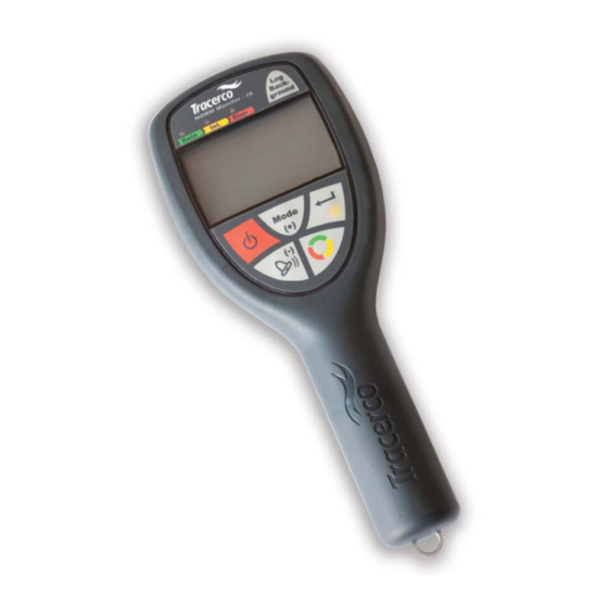
Page 16: Tracerco Norm Monitor-Is - Functional Description
4 Tracerco NORM Monitor-IS – Functional description 4.1 Handset monitor control keys Figure 3 - Tracerco NORM Monitor–IS – key definitions MN1007-C... - Page 17 Analogue / Digital Screen Digital readout displays radiation levels detected by the probe in user selectable units. The LEDs provide operational status information. Analogue dial representation provides an animated auto-ranging readout. The meter may be configured to show counts (cps or cpm), dose rate (µSv/h or µR/h) or Bq/cm Instrument on/off key Push key to turn the monitor power on or off.
- Page 18 15 seconds). The user is presented with a time-averaged result on the display which gradually finds a mean value over the duration of the measurement Colour-coded LEDs above the instrument’s display screen indicate the current status of this measurement process. [See Section 4.5 for more details on the integration function] Select/Backlight key The dual function key is used to select options from the alarm and integrate menus as well as activate the display...
- Page 19 To use any of the background adjusted modes of operation (including Bq/cm , the user must take a background reading for the chosen probe. [See section 4.7 for further information on background measurement] Probe Connection Each probe is supplied with a flying lead terminated with an industrial specification IP68 (mated condition) coupling connector [See Section 4.2.1 –...
-
Page 20: Operating The Instrument
4.2 Operating the instrument 4.2.1 Connecting the probes Each probe is supplied with a flexible (“curly”) cable terminated with a polarised industrial grade plug. Connection to the hand-held monitor is made via a panel mount socket connection as shown below. ... -
Page 21: Switching On The Instrument
4.2.3 Switching on the instrument Pressing the power key will turn on the monitor. A self-test routine enables all LCD segments and the three indicator LEDs are illuminated in sequence. Following the initialisation, visual acknowledgement of the selected probe type is displayed briefly as illustrated below. -
Page 22: Measurement Modes For The Scintillator Probe
Measurement Modes for the Scintillator Probe. Following initialisation – see previous section - the user may choose to change the measurement unit mode. The various measurement modes for the scintillator probe are: cps count rate (or cpm) background subtracted cps count rate (or cpm) ... -
Page 23: Cps Minus Background Mode
cps Minus Background Mode 4.3.2 Press the Mode key to change the measuring units from cps to cps minus background mode. The display shows a bar graph as well as digital readout. The measurement units and mode are indicated by the “cps”... -
Page 24: Modes Of Operation For The Geiger Müller Probe
Figure 8 - Dose rate screen with US units The green LED indicates that the instrument is recording data in real-time. 4.4 Modes of Operation for the Geiger Müller Probe. Following initialisation – Section 4.2.4 - the user may choose to change the measurement unit mode. The various measurement modes for the Geiger Müller probe are: ... -
Page 25: Cps Minus Background Mode
cps Minus Background Mode 4.4.2 Press the Mode key to change the measuring units from cps to cps minus background mode. The display shows an analogue scale and digital numeral readout. The measurement units and mode are indicated by the “cps” and “– Background” text. In this mode the digital display will show the cps count rate with the last stored background count subtracted. -
Page 26: Figure 11 - Radionuclide Selection In Bq/Cm 2 Mode
4.4.3.1 Selecting the radionuclide 1. Select Bq/m mode by repeatedly pressing the Mode key. 2. Press the Select key to enter the nuclide selection menu 3. Press the Mode key to cycle through the radionuclide options. 4. Return to the Bq/cm reading screen by pressing the Select key Figure 11 - Radionuclide selection in Bq/cm mode... -
Page 27: Integration Function
4.5 Integration Function Each of the operating modes detailed in the above sections may utilise the integration measurement function. Example – Making an integrated count measurement in cps mode 4.5.1 Figure 13 - cps integration screen A single press of the Rate/Int./Stop key starts the integrated cps measurement. -
Page 28: Alarm Activation In Integration Mode
4.6 Alarm activation in integration mode Whilst making an integrated measurement, alarm activation will not be invoked until after the integration period has expired. If at the end of the integration period the alarm level is exceeded, then all three indicator LEDs will flash in unison and the sounder will be activated. -
Page 29: Background Measurement
4.7 Background Measurement It is good practice to update the background value held in the instrument at regular intervals; particularly where there has been a significant change in the environment where monitoring work is being carried out; or where the operator is uncertain of the value held in memory. -
Page 30: Alarm Configuration
4.8 Alarm Configuration Alarm levels may be configured for each measurement mode (cps (or cpm); µSv/h (or µR/h); Bq/cm ) and are retained in memory following power down or battery replacement. The levels apply to the probe type connected. For example, the cps alarm level configured for the scintillation (SA50) probe may be given a different value to that of the corresponding cps alarm level for the GM probe. -
Page 31: Selecting The Alarm Type
Pressing the mode key will toggle the alarm ON / OFF condition. If the screen display shows A-OFF, pressing the Select key will return the instrument to the measuring mode. Note: that the alarm activation will only relate to the instrument’s current measuring mode. i.e. cps, Bq/cm Dose Rate. -
Page 32: Setting Alarm Parameters
Setting Alarm Parameters LEVELs Alarm LEVELs are entered as a numeric value and are related directly to the value which is displayed on the instrument for the relevant measurement mode. Having previously selected the LEVEL/FACt preference, press the Select key and use the Mode (+) Alarm (-) keys to increase or decrease the value displayed. -
Page 33: Alarm Options For Each Measurement Mode
4.8.1 Alarm options for each measurement mode Table 6 – Complete set of alarm options Operating mode Alarm type Description Level Alarm activated when total cps exceeds user-configured level cps - background Level Alarm activated when cps above background radiation exceeds user- configured level cps - background Factor... -
Page 34: Adjusting The Integration Period
5 Adjusting the integration period The versatility of the integration function is enhanced by the facility to configure the period over which the measurement is taken. When the detected count rate is low, it may be advantageous to take a measurement over an extended period; thereby minimising the statistical error by giving an averaged count rate over the sample period. - Page 35 Selection of the option provides the operator with a screen showing the current integration period in seconds. The +/- keys ( ) may now be used to adjust the period within the range 0 to 600 seconds. Note. In the unlikely event that the user wishes to disable the integration button function, then setting the integration period to “0”...
-
Page 36: Locking The Keypad
6 Locking the keypad The operator, or supervisor, has the capability to lock the instrument keypad so that only essential functions are enabled. A combinational key-press locks out the Mode and Select functions thus leaving the operator with a single-mode- use instrument. -
Page 37: Using The Instrument - Taking A Norm Measurement
7 Using the Instrument – taking a NORM measurement Measurements of radioactivity at levels which are only slightly greater than background are subject to significant statistical uncertainty. A more precise result can be achieved by using the monitor in integration mode which allows counts to be accumulated over a fixed time period. - Page 38 2. Select units. Using the Mode key, cycle through the various options associated with each probe type. For the SA-50 scintillation probe the options are: Cps with background subtracted µSv/h µSv/h with background subtracted 3. Press Rate/Int./Stop key.
-
Page 39: Faults /Troubleshooting
Tracerco for repair. Low count rate After 20 seconds of zero counts… Move to an area of higher activity. detected – possible If error persists, return to Tracerco for failure of probe diagnosis detector element or cable Further 20 seconds…... -
Page 40: Display Ranges - Reading The Screen
9 Display ranges – reading the screen The following images illustrate the range of the instrument according to each measurement unit selection. Figure 22 - Display ranges MN1007-C... -
Page 41: Maintenance And Calibration
The user is advised not to open the NORM Monitor-IS or any of its associated probes. The NORM Monitor-IS kit has no serviceable parts and should be returned to Tracerco in the event of damage. It is essential for safety integrity, that repair of this ATEX certified equipment is carried out by qualified personnel in accordance with the appropriate standards and regulations. -
Page 42: Equipment Inspection
All NORM Monitor-IS probes are checked and calibrated immediately prior to despatch to the customer. Following this initial procedure (or the regular inspection and calibration check), Tracerco engineers will set the next calibration check due date within the probe’s memory. -
Page 43: Essential Safety Information For Hazardous Areas
11 Essential Safety Information For Hazardous Areas The NORM Monitor-IS handset and probes are safe for use in hazardous areas described in the equipment marking and according to the essential safety information stated below. Note: Approval dependant on product version ordered and described on equipment label. Marking details ATEX Certificate number: Baseefa12ATEX0209X IECEx Certificate number: IECExBAS12.0114X... -
Page 44: Contact Us
+603 7803 4622 (GL) Tel: tracerco.asia@tracerco.com Email: Houston, USA +1 281 291 7769 Tel: tracerco@tracerco.com Email: Perth, Australia +61 (0)8 9209 3905 Tel: tracerco@tracerco.com Email: Please visit the Tracerco website www.tracerco.com for details of other Tracerco offices and locations. MN1007-C... - Page 45 Tracerco manufacture a wide range of intrinsically safe and standard ration monitoring products. Tracerco can provide a professional, rapid turnaround calibration and repair service as well as offering a hire service for a range of monitors. Our experience technicians can also provide an annual Hazardous Area Equipment Inspection as described by...
-
Page 46: Technical Specification
13 Technical Specification 13.1 Radiological Type Tests Table 9 - Radiological type test Instrument Applicable standard Description NORM Monitor-IS with Geiger BS EN 60325:2004 Radiation Protection Instrumentation – Alpha, probe Beta and Alpha/Beta (Beta 60keV) contamination meters and monitors NORM Monitor-IS with Scintillation BS EN 62363:2011 Radiation protection instrumentation –... -
Page 47: Environmental
13.5 Environmental Table 13 - Environmental specification Operating Temperature -20 to +50°C Storage Temperature -20 to +50°C Humidity 0 – 95% Shock Drop tests according to BS EN 60079-0 Vibration EN ISO 13628-6:2006. 30g, 11ms Ingress protection: Scintillator probe IP67 Geiger probe IP34 Handset meter... -
Page 48: Hazardous Area Approval
13.7 Hazardous area approval Table 16 - Hazardous area approval ATEX certificate reference: 12ATEX0209X Certification numbers IECEx certificate reference: IECExBAS12.0114X CSA certificate reference: CSA.13.2616487 II 1G ATEX / IECEx Equipment mark Ex ia IIC T4 Ga (-20°C Ta +50°C) Class I, Div 1, Groups A, B, C, D;... -
Page 49: Appendix 1 - Decay Series For Uranium And Thorium
Appendix 1 – Decay Series for Uranium and Thorium Figure 23 - U-238 Decay chain MN1007-C... -
Page 50: Figure 24 - U235 Decay Chain
Figure 24 - U235 Decay Chain MN1007-C... -
Page 51: Figure 25 - Thorium-232 Decay Chain
Figure 25 - Thorium-232 Decay Chain MN1007-C... -
Page 52: Appendix 2. - Menu Diagrams
14 Appendix 2. - Menu diagrams 14.1 Scintillator probe Menu Figure 26 - Complete scintillator probe menu MN1007-C... -
Page 53: Geiger Probe Menu
14.2 Geiger Probe Menu Figure 27 - Complete Geiger probe menu MN1007-C... -
Page 54: Alarm Menu
14.3 Alarm Menu Figure 28 - Complete alarm menu MN1007-C... -
Page 55: Document Revision History
15 Document Revision History Document Date Revision description Author number MN1007-A 24/01/13 First release MN1007-B 10/06/13 CSA approval details added. Essential safety combined MN1007-C...
Need help?
Do you have a question about the NORM Monitor IS and is the answer not in the manual?
Questions and answers