
Related Manuals for VIGILEC Vigilec mini V1N

Summary of Contents for VIGILEC Vigilec mini V1N
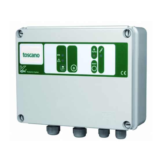
- Page 1 INSTALLATION AND OPERATION Mod. Vigilec mini (V1N) Mod. Vigilec mono (V1M) Pump controller and protection for one pump Multicontrol +info: www.vigilec.com...
-
Page 2: Main Features
Alarm trip in 7 s. (overload) • Multicontrol. or in 4 s. (underload). • Vigilec mini: Three-phase. 230/400 V~. Direct- • Protection against pump jamming during long on-line starting (DOL). rest periods (only in AUTO mode). •... -
Page 3: Front Confi Guration
Front confi guration START button: AUTOMATIC mode (green circle Led ON): press the button and the unit will work automatically with the established controls and protections. MANUAL mode (green circle Led fl ashing): holding down the button more than 4 seconds, the pump is forced to start running. -
Page 4: Internal Confi Guration
Internal confi guration Mod. Vigilec mono Control fuse (0,1A). Current transformer. Power relay. Flat cable connector. Minimum current adjustment (Amp. min). Maximum current adjustment (Amp. max). Control terminal blocks. Capacitor housing (submersible pumps). Main supply cable gland. Motor cable gland. -
Page 5: Installation
Clevis screws to box Clevis (Backside) screws CLEVIS Mod. Vigilec mono to wall Single phase supply Single phase motor output Single phase motor output + capa- citor U V W Mod. Vigilec mini Three phase supply... - Page 6 Probes installation Two probes One probe Without probes The wires must be in- sulated. maximum lenght for probes wiring is 200 mts. and the minimum section is 0,5 mm². A CORRECT EARTH CONNECTION is essen- tial for the effective opera- tion of the level control.
-
Page 7: Unit Operation
Unit operation TWO PROBES The pump starts when the water level exceeds the high level probe (orange led off), and stops when the water level descends below the low level probe (orange led on). ONE PROBE When the water level des- cends below the low level probe, the pump stops. - Page 8 WITHOUT PROBES A correct minimum current ad- justment is essential. (see section “CURRENT ADJUSTMENTS”) When the level approaches the pump intake, the effort done by the min. pump decreases. The unit uses the motor as sensor: when this one de- creases the effort, the intensity con- sumed decreases.
- Page 9 Current adjustments LIGHT FLASHING LIGHT OFF LITH ON OVERLOAD adjustment (maximum current) If the warning light is still on... Turn to the Turn slowly to the left Turn right until the right until the warning light warning light swit- starts fl ashing. ches off ...
-
Page 10: Specifications
Specifi cations Vigilec mono (V1M) Vigilec mini (V1N) Supply voltage 230 V~ 230/400 V~ (selectable) Admissible voltage variation ±20% (>30%: auto power-off) ±20% (>30%: auto power-off) Maximum intensity 18 Amp AC3 12 Amp AC3 (16 or 23 a/model) Overload adjustment (Amp. max) -
Page 11: Troubleshooting
• Motor not connected. • Connect the motor. • Input phase failure (Vigilec mini). • Check the three supply phases. • Abnormal excessive motor con- • Check the motor. The motor is over- sumption. - Page 12 INSTRUCCIONES DE INSTALACION Y USO NOTICE D’INSTALLATION ET DE MISE EN SERVICE INSTRUÇÕES DE INSTALAÇÃO E USO MANUALI DI INSTRUZIONE INSTALLATIONSHINWEISE UND INBETRIEBNAHME HANDLEIDING VOOR INSTALLATIE EN GEBRUIK www.vigilec.com ΕΓΚΑΤΑΣΤΑΣΗ ΚΑΙ ΧΡΗΣΗ KURULUM VE KULLANIM ASENNUS JA KÄYTTÖ ОБЛАСТЬ ПРИМЕНЕНИЯ И УСТАНОВКА ﻡﺍﺩﺥﺕﺱﺍﻝﺍﻭ ﺕﻱﺏﺙﺕﻝﺍ...
Need help?
Do you have a question about the Vigilec mini V1N and is the answer not in the manual?
Questions and answers