
Summary of Contents for Interroll BM 8350
- Page 1 Installation and Operating Instructions Interroll 24 V Belt Conveyor Straight / curve BM 8350 / BM 8360 Version 1.1 (02/2016) en-US Translation of original instruction manual...
- Page 2 Copyright of installation and operating instructions The copyright of these installation and operating instructions remains with Interroll Automation GmbH. The installation and operating instructions contain technical regulations and drawings which may not be reproduced partially or in full, transmitted by any means, utilized without permission for competitive purposes or disclosed to third parties.
-
Page 3: Table Of Contents
Interfaces to other devices ...................... 9 Operating modes .......................... 10 Normal mode.......................... 10 Special mode.......................... 10 Product identification.................... 11 24 V Belt Conveyor Straight BM 8350 ................... 11 Components.......................... 11 Property ............................ 12 Technical data .......................... 13 24 V Belt Conveyor Curve BM 8360.................. 14 Components.......................... - Page 4 Interroll 24 V belt conveyor straight / curve BM 8350 / BM 8360 Table of contents Installation ........................ 21 To be observed during installation.................... 22 Torque............................ 22 Grounding.......................... 22 Orientation.......................... 22 Connection .......................... 22 Anchoring ........................... 22 Integration into complete system .................. 22 Installing supports .......................... 23...
- Page 5 Interroll 24 V belt conveyor straight / curve BM 8350 / BM 8360 Maintenance intervals ........................ 63 Maintenance and inspection list.................... 63 Troubleshooting...................... 64 In case of a fault .......................... 64 Troubleshooting .......................... 64 Spare and wear parts .................... 65 Ordering information ........................ 65 Spare part drawing BM 8350.................... 65 Spare parts list BM 8350 ...................... 66...
-
Page 6: Introduction
Interroll does not accept any liability for faults or defects due to non-observance of these installation and operating instructions. If you have any questions after reading the installation and operating instructions, please contact the Interroll customer service. Contact persons close to you can be found on the Internet under: www.interroll.com/contacts. Version 1.1 (02/2016) en-US... -
Page 7: Warning Notices In This Document
Interroll 24 V belt conveyor straight / curve BM 8350 / BM 8360 Introduction Warning notices in this document The warning notices refer to risks which may arise while using the module. They are available in four danger levels identified by the signal word:... -
Page 8: Safety
Interroll 24 V belt conveyor straight / curve BM 8350 / BM 8360 Safety State of the art The module has been built to comply with the state of the art. Nevertheless, users may encounter hazards during its use. Disregarding the notices in this manual may lead to serious injury. -
Page 9: Dangers
Interroll 24 V belt conveyor straight / curve BM 8350 / BM 8360 Safety Dangers The following list informs you about the various types of danger or damage that may occur while working with the module. 4 Perform any maintenance and repair work on the module only in de-energized state and Safety devices ensure that it cannot be started accidentally. -
Page 10: Operating Modes
Interroll 24 V belt conveyor straight / curve BM 8350 / BM 8360 Safety Operating modes Normal mode The module is installed at the customer in a complete system and operated as part of the system. Special mode Special operation refers to all operating modes which are required to guarantee and maintain regular operation. -
Page 11: Product Identification
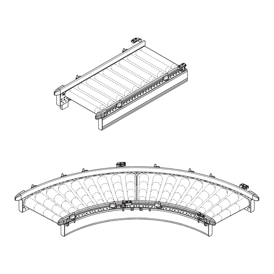
Interroll 24 V belt conveyor straight / curve BM 8350 / BM 8360 Product identification 24 V Belt Conveyor Straight BM 8350 Components 13 12 11 10 24 V belt conveyor straight BM 8350 Drive roller Side frame (C-profile) Carrying idler... -
Page 12: Property
Interroll 24 V belt conveyor straight / curve BM 8350 / BM 8360 Product identification Property The 24 V belt conveyor is a belt conveyor that is divided into zones and operates with zero pressure accumulation; its drive is based on the 24 V RollerDrive. It is possible to transport and accumulate small products, as well as products not suitable for roller tracks. -
Page 13: Technical Data
Interroll 24 V belt conveyor straight / curve BM 8350 / BM 8360 Product identification Technical data Straight Belt Conveyor Light BM 8350 Max. load capacity per zone 50 kg Conveying speed Max. 0.8 m/s Ambient temperature +5 to +40 °C... -
Page 14: 24 V Belt Conveyor Curve Bm 8360
Interroll 24 V belt conveyor straight / curve BM 8350 / BM 8360 Product identification 24 V Belt Conveyor Curve BM 8360 Components 24 V belt conveyor curve BM 8360 Conical carrying idler Universal support Conical drive roller Side cover... -
Page 15: Property
Interroll 24 V belt conveyor straight / curve BM 8350 / BM 8360 Product identification Property The 24 V belt conveyor curve is a belt curve that is divided into zones and operates with zero pressure accumulation; its drive is based on the 24 V RollerDrive. It is possible to transport and store small products, as well as products not suitable for roller tracks. -
Page 16: Technical Data
Interroll 24 V belt conveyor straight / curve BM 8350 / BM 8360 Product identification Technical data Belt Curve Light BM 8360 Max. load capacity per zone 20 kg Conveying speed Max. 0.5 m/s Ambient temperature +5 to +40 °C... -
Page 17: Scope Of Supply
Interroll 24 V belt conveyor straight / curve BM 8350 / BM 8360 Product identification Scope of supply The 24 V belt conveyor is completely assembled and wired in its delivery state. The scope of supply includes: • Rack, including side frames, cross ties, side covers •... -
Page 18: Nameplate
Interroll 24 V belt conveyor straight / curve BM 8350 / BM 8360 Product identification Nameplate Nameplate (with arrow in transport direction) Arrow in transport direction Year of construction Type designation Company address Machine no. Weight in kg Layout item no. -
Page 19: Transport And Storage
Interroll 24 V belt conveyor straight / curve BM 8350 / BM 8360 Transport and storage Transport WARNING Risk of injury during transport 4 Fix the module securely and slip-proof for the transport. 4 Ensure that the lifting device (crane, fork lift, etc.) is rated for the weight of the module. -
Page 20: Storage
Interroll 24 V belt conveyor straight / curve BM 8350 / BM 8360 Transport and storage Storage WARNING Risk of injury due to improper storage 4 Do not stack modules. Do not place any other objects on the module. 4 Check module for stability. -
Page 21: Installation
Interroll 24 V belt conveyor straight / curve BM 8350 / BM 8360 Installation WARNING Risk of injury due to improper assembly 4 Mechanical assembly tasks should be performed only by service personnel. Observe the safety information. 4 Electrical assembly tasks should be performed only by authorized electricians. Observe the safety information. -
Page 22: To Be Observed During Installation
Interroll 24 V belt conveyor straight / curve BM 8350 / BM 8360 Installation To be observed during installation Torque When tightening screws and nuts, always observe the standard tightening torque, unless specifically indicated otherwise. Standard screw lockers should be replaced as needed. -
Page 23: Installing Supports
Interroll 24 V belt conveyor straight / curve BM 8350 / BM 8360 Installation Installing supports Support with two height-adjustable feet Serrated flange bolts Height-adjustable foot CAUTION Risk of injury when lifting heavy loads 4 During the installation and replacement of conveyor modules or heavy spare parts, work in pairs or use a suitable carriage. -
Page 24: Connecting The Modules
Interroll 24 V belt conveyor straight / curve BM 8350 / BM 8360 Installation Connecting the modules Side cover Profile connectors Screws Side frame CAUTION Risk of crushing and injuries from cuts 4 When integrating the module into a complete system, consider possible danger spots, particularly infeed locations and interfaces. - Page 25 Interroll 24 V belt conveyor straight / curve BM 8350 / BM 8360 Installation 4 To connect sections for irregular pitches, use profile connectors with elongated holes and without punch pressing. 4 Position the modules to be connected so that the side frames (4) are aligned.
-
Page 26: Installing The Side Guide Profiles
Interroll 24 V belt conveyor straight / curve BM 8350 / BM 8360 Installation Installing the side guide profiles Side guide profile Flexible universal support Side guide support Rigid universal support Mounting bracket CAUTION Risk of crushing due to circulating conveyor belt! 4 Install side guide profiles for 24 V belt conveyor straight and curve lying directly on the side frame. -
Page 27: Installing The Rigid Universal Support
Interroll 24 V belt conveyor straight / curve BM 8350 / BM 8360 Installation For installing the side guide profiles on the 24 V belt conveyor curve, rigid universal supports are used on the inside and flexible universal supports on the outside. -
Page 28: Installing The Flexible Universal Support
Interroll 24 V belt conveyor straight / curve BM 8350 / BM 8360 Installation Installing the flexible universal support Side guide profile Mounting bracket Side cover Hexagon head screws Clamping plate Universal support cover Side guide support The flexible universal supports can be delivered pre-assembled upon request. In this case, the... - Page 29 Interroll 24 V belt conveyor straight / curve BM 8350 / BM 8360 Installation 4 Loosen side cover (2) from the side frame. 4 Swing up the cover (7) of the universal support. 4 Loosen hexagon head screws (6) in the universal support, but do not remove them.
-
Page 30: Fastening The Side Guide Profile On The Universal Support
Interroll 24 V belt conveyor straight / curve BM 8350 / BM 8360 Installation Fastening the side guide profile on the universal support Side guide profile Flexible universal support Side guide support Rigid universal support Mounting bracket 4 Break out the upper hole cover in the side guide support. - Page 31 Interroll 24 V belt conveyor straight / curve BM 8350 / BM 8360 Installation 4 Close the cover of the side guide support and snap it in place. Version 1.1 (02/2016) en-US Translation of original instruction manual...
-
Page 32: Installing The Photo Cell And Reflector
Interroll 24 V belt conveyor straight / curve BM 8350 / BM 8360 Installation Installing the photo cell and reflector Mounting bracket Side guide profile Mounting plate Reflector Photo cell The photo cell and the reflector are each delivered as a finished unit: •... - Page 33 Interroll 24 V belt conveyor straight / curve BM 8350 / BM 8360 Installation 4 Fasten photo cell or reflector to mounting plate: Place the strap on the mounting cam at the underside of the photo cell/reflector and snap it into place.
-
Page 34: Installing Side Cover And End Caps
Interroll 24 V belt conveyor straight / curve BM 8350 / BM 8360 Installation Installing side cover and end caps End caps Side cover 4 Snap side cover (2) into the C-profile of the side frame. 4 Push end caps (1) into the C-profile of the side frame. -
Page 35: Initial Startup And Operation
Interroll 24 V belt conveyor straight / curve BM 8350 / BM 8360 Initial startup and operation Initial startup WARNING Risk of injuries due to incorrect handling 4 Check electrical connections and protective devices. 4 Remove the materials from the module. -
Page 36: Cleaning
Interroll 24 V belt conveyor straight / curve BM 8350 / BM 8360 Cleaning WARNING Risk of injuries due to incorrect handling 4 Only perform cleaning work on the module after you have switched off the power. Switch off the voltage supply and ensure that it cannot be started accidentally. -
Page 37: Maintenance And Repair
Interroll 24 V belt conveyor straight / curve BM 8350 / BM 8360 Maintenance and repair Observe the following for maintenance and repair WARNING Risk of crushing and injuries 4 Ensure that the personnel involved in maintenance and repair have secure footing and sufficient room to move. -
Page 38: Straight Travel And Belt Tension
Interroll 24 V belt conveyor straight / curve BM 8350 / BM 8360 Maintenance and repair Straight travel and belt tension Straight travel Straight travel is ensured by a taper strip on the inside of the belt and does not have to be implemented using belt tension. -
Page 39: Adjusting The Belt Tension In The Curve Section
Interroll 24 V belt conveyor straight / curve BM 8350 / BM 8360 Maintenance and repair Adjusting the belt tension in the curve section Tensioning device at the 24 V belt conveyor curve Adjusting nut Locknut Requirement: The module is out of operation. -
Page 40: Replacing The Carrying Idler
Interroll 24 V belt conveyor straight / curve BM 8350 / BM 8360 Maintenance and repair Replacing the carrying idler Replacing the carrying idler in the straight section Belt Closing clip Carrying idler Requirement: The module is out of operation. -
Page 41: Replacing The Carrying Idler In The Curve Section
Interroll 24 V belt conveyor straight / curve BM 8350 / BM 8360 Maintenance and repair Replacing the carrying idler in the curve section Carrying idler Belt Serrated flange bolts Requirement: The module is out of operation. 4 Remove the side cover on both sides. -
Page 42: Replacing The Tensioning Roller
Interroll 24 V belt conveyor straight / curve BM 8350 / BM 8360 Maintenance and repair Replacing the tensioning roller Replacing the tensioning roller in the straight section Tensioning device Nuts Pivot heads Tensioning screw Tensioning roller Requirement: The module is out of operation. -
Page 43: Replacing The Tensioning Roller In The Curve Section
Interroll 24 V belt conveyor straight / curve BM 8350 / BM 8360 Maintenance and repair Replacing the tensioning roller in the curve section Tensioning device Tensioning screws Pivot heads Tensioning roller Requirement: The module is out of operation. 4 Remove the side cover on both sides. -
Page 44: Replacing The Drive Roller
Interroll 24 V belt conveyor straight / curve BM 8350 / BM 8360 Maintenance and repair Replacing the drive roller Replacing the drive roller in the straight section Side cover Motor connecting cable Ribbed nut Closing clip Control Drive roller... - Page 45 Interroll 24 V belt conveyor straight / curve BM 8350 / BM 8360 Maintenance and repair 4 Plug motor connecting cable onto control card. 4 Adjust the belt tension, See "Adjusting belt tension in straight section", page 38. 4 Attach the side cover.
-
Page 46: Replacing The Drive Roller In The Curve Section
Interroll 24 V belt conveyor straight / curve BM 8350 / BM 8360 Maintenance and repair Replacing the drive roller in the curve section Drive roller Tensioning screw Motor connecting cable Pivot heads Ribbed nut Nuts Control In the 24 V belt conveyor curve, the drive roller is fastened on the outside of the curve with a ribbed nut (3) and on the inside with a pivot head (6) in a tensioning device. - Page 47 Interroll 24 V belt conveyor straight / curve BM 8350 / BM 8360 Maintenance and repair 4 Remove the side cover on both sides. 4 Loosen the belt tension, See "Adjusting the belt tension in the curve section", page 39. 4 Pull motor connecting cable (2) off of the control system (4) or the extension cable.
-
Page 48: Replacing The Conveyor Belt
Interroll 24 V belt conveyor straight / curve BM 8350 / BM 8360 Maintenance and repair Replacing the conveyor belt Replacing the conveyor belt in the straight section Replacing the conveyor belt for the 24 V belt conveyor straight Side cover... - Page 49 Interroll 24 V belt conveyor straight / curve BM 8350 / BM 8360 Maintenance and repair 4 Pull off old conveyor belt (3) on the open non-cable side from the drive roller (5) and tensioning roller (2) and dispose of it properly.
-
Page 50: Replacing The Conveyor Belt In The Curve Section
Interroll 24 V belt conveyor straight / curve BM 8350 / BM 8360 Maintenance and repair Replacing the conveyor belt in the curve section Replacing the conveyor belt for the 24 V belt conveyor curve Side cover Drive roller Tensioning screw... - Page 51 Interroll 24 V belt conveyor straight / curve BM 8350 / BM 8360 Maintenance and repair 4 Unscrew the nuts at all three tensioning devices (6) of the respective zones and laterally pull out the tensioning screws (2). 4 For the drive roller (5), loosen the ribbed nut in the respective zone on the cable side (outside) (do not remove) and remove ribbed screw on the inside, See "Replacing the drive...
-
Page 52: Replacing The Roller Clip
Interroll 24 V belt conveyor straight / curve BM 8350 / BM 8360 Maintenance and repair Replacing the roller clip Closing clip in the side frame Roller Closing clip CAUTION Risk of crushing from rotating parts 4 Before any assembly and maintenance work, the respective devices must be decommissioned and disconnected from the voltage supply. -
Page 53: Replacing The Photo Cell
Interroll 24 V belt conveyor straight / curve BM 8350 / BM 8360 Maintenance and repair Replacing the photo cell Photo cell with detail view of underside Mounting bracket Side guide profile Mounting plate Reflector Photo cell The photo cell holder is fitted with a setscrew to be able to adjust the photo cell vertically on the mounting bracket. - Page 54 Interroll 24 V belt conveyor straight / curve BM 8350 / BM 8360 Maintenance and repair 4 Check whether both LEDs are lit. 4 If the yellow LED flashes, position reflector and photo cell to each other. LED green LED yellow Meaning Photo cell is operational.
-
Page 55: Replacing The Reflector
Interroll 24 V belt conveyor straight / curve BM 8350 / BM 8360 Maintenance and repair Replacing the reflector Photo cell with detail view of underside Mounting bracket Side guide profile Mounting plate Reflector Photo cell Reflector and reflector holder are replaced together: 4 Pull strap off of the fastening cams of the reflector. -
Page 56: Replacing The Side Guide Profile
Interroll 24 V belt conveyor straight / curve BM 8350 / BM 8360 Maintenance and repair Replacing the side guide profile Flexible universal support with detailed view of side guide support at side guide profile Side guide profile Hexagon nut... -
Page 57: Replacing The Side Guide Support
Interroll 24 V belt conveyor straight / curve BM 8350 / BM 8360 Maintenance and repair Replacing the side guide support Side guide profile Side guide support cover Side guide support Mounting bracket Hammer head bolt Flexible universal support Hexagon nut Requirement: The module is out of operation. - Page 58 Interroll 24 V belt conveyor straight / curve BM 8350 / BM 8360 Maintenance and repair 4 Loosen the hexagon nut at the new side guide support, but do not remove it. Create sufficient clearance so that the hammer head bolt can later be inserted into the side profile and the clamp can be pushed onto the mounting bracket.
-
Page 59: Replacing The Flexible Universal Support
Interroll 24 V belt conveyor straight / curve BM 8350 / BM 8360 Maintenance and repair Replacing the flexible universal support Side guide profile Mounting bracket Side cover Hex nuts Clamping plate Universal support cover Side guide support Requirement: The module is out of operation. - Page 60 Interroll 24 V belt conveyor straight / curve BM 8350 / BM 8360 Maintenance and repair 4 Slightly turn the clamping plate (3) with the complete universal support and remove it from the C-profile of the side frame. 4 Loosen the hexagon head screws at the new universal support, but do not remove it.
-
Page 61: Replacing The Side Cover
Interroll 24 V belt conveyor straight / curve BM 8350 / BM 8360 Maintenance and repair Replacing the side cover End cap Side cover 4 Carefully pry out the side cover (2) out of the side profile at one end using a tool (e.g. -
Page 62: Replacing The End Cap
Interroll 24 V belt conveyor straight / curve BM 8350 / BM 8360 Maintenance and repair Replacing the end cap End cap Side cover 4 Remove end caps (1) from the side frame using a tool (e.g. screwdriver). 4 Push the new end caps into the C-profile of the side frame. -
Page 63: Maintenance Intervals
Interroll 24 V belt conveyor straight / curve BM 8350 / BM 8360 Maintenance and repair Maintenance intervals If maintenance is not performed according to schedule, it may lead to damages and failures. If maintenance intervals are not followed, the warranty will be void. -
Page 64: Troubleshooting
Interroll 24 V belt conveyor straight / curve BM 8350 / BM 8360 Troubleshooting In case of a fault DANGER Danger - electrocution 4 Only perform maintenance and repair work after you have switched off the power. 4 Faults on electrical equipment may be removed only by a trained electrician! -
Page 65: Spare And Wear Parts
BM 8350 / BM 8360 Spare and wear parts All spare and wear parts are available from Interroll. Maintenance and repair work may be performed only by qualified personnel. Interroll offers training sessions about required maintenance and repair tasks upon request. -
Page 66: Spare Parts List Bm 8350
Interroll 24 V belt conveyor straight / curve BM 8350 / BM 8360 Spare and wear parts Spare parts list BM 8350 S = spare part, W = wear part, T = tool Type: BM 8350 Item no.: Designation Comment... -
Page 67: Spare Part Drawing Bm 8360
Interroll 24 V belt conveyor straight / curve BM 8350 / BM 8360 Spare and wear parts Spare part drawing BM 8360 4 11 24 V belt conveyor curve BM 8360 Version 1.1 (02/2016) en-US Translation of original instruction manual... -
Page 68: Spare Parts List Bm 8360
Interroll 24 V belt conveyor straight / curve BM 8350 / BM 8360 Spare and wear parts Spare parts list BM 8360 S = spare part, W = wear part, T = tool Type: BM 8360 Item no.: Designation Comment... -
Page 69: Decommissioning And Disposal
Interroll 24 V belt conveyor straight / curve BM 8350 / BM 8360 Decommissioning and disposal 4 When disposing the motor oil, observe the disposal documents of the motor manufacturer. 4 The packaging must be recycled to provide environmental relief. -
Page 70: Installation Declaration
EU Machinery Directive: • Interroll 24 V belt conveyor straight BM 8350 • Interroll 24 V belt conveyor curve BM 8360 Important Note! The incomplete machine may only be put into operation if it has been determined that the overall machine/system, into which the incomplete machine is to be installed, meets the requirements of this directive. - Page 71 Interroll 24 V belt conveyor straight / curve BM 8350 / BM 8360 Version 1.1 (02/2016) Translation of original instruction manual...
- Page 72 © copyright For your local contacts please visit Version 1.1 (02/2016) interroll.com/contacts Translation of original instruction manual...
Need help?
Do you have a question about the BM 8350 and is the answer not in the manual?
Questions and answers