Table of Contents
Advertisement
Quick Links
F4T Touch Screen Controller
TestEquity LLC
6100 Condor Drive
Moorpark, CA 93021
Support:
877-512-3457 Toll Free
805-480-0638
Corporate:
800-732-3457
805-498-9933
http://www.testequity.com
Copyright © 2014-16 TestEquity LLC
Portions of this manual are used with permission from Watlow Electric Manufacturing Company, 2014-16
User's Guide
Revision 3.0 Firmware
Rev. 2.03 – October 31, 2016
Advertisement
Table of Contents

Related Manuals for TestEquity F4T

Summary of Contents for TestEquity F4T
- Page 1 F4T Touch Screen Controller User’s Guide Revision 3.0 Firmware TestEquity LLC 6100 Condor Drive Moorpark, CA 93021 Support: 877-512-3457 Toll Free 805-480-0638 Corporate: 800-732-3457 805-498-9933 http://www.testequity.com Copyright © 2014-16 TestEquity LLC Rev. 2.03 – October 31, 2016 Portions of this manual are used with permission from Watlow Electric Manufacturing Company, 2014-16...
-
Page 3: Table Of Contents
Table of Contents Chapter 1 – Safety Instructions __________________________________________________5 Introduction _____________________________________________________________________ 5 Safety Notices ____________________________________________________________________ 5 Chapter 2 – Using the F4T Front Panel ___________________________________________7 F4T Menus ______________________________________________________________________ 7 Understanding F4T Menus _________________________________________________________________ 7 Event Driven Menus ______________________________________________________________________ 7 Navigating and Understanding the User Interface ______________________________________ 8... - Page 4 Serial Modbus-to-GPIB Converter __________________________________________________________ 50 Serial Modbus-to-Ethernet Converter ________________________________________________________ 50 Programming Syntax for the F4T Controller, Data Map 1 ________________________________________ 51 Programming Syntax for the F4T Controller, Data Map 2 ________________________________________ 52 Chapter 5 – Event Board Option TE-0033 ________________________________________53...
-
Page 5: Chapter 1 - Safety Instructions
Improper modifications to these setup values can result in erratic performance and unreliable operation. Setup examples in the Watlow F4T Manuals are NOT applicable to this chamber. Do not attempt to modify the setup values, unless you thoroughly understand what you are doing. -
Page 7: Chapter 2 - Using The F4T Front Panel
This chapter is designed to give you a better understanding of the structure and navigation of the F4T menus as viewed from the front panel. Understanding F4T Menus The graphic below illustrates at a high level the structure of the F4T menus. Event Driven Menus During normal operation it is possible that an event can occur that will present the user with indications, pop-up windows and menu selections that are not shown above. -
Page 8: Navigating And Understanding The User Interface
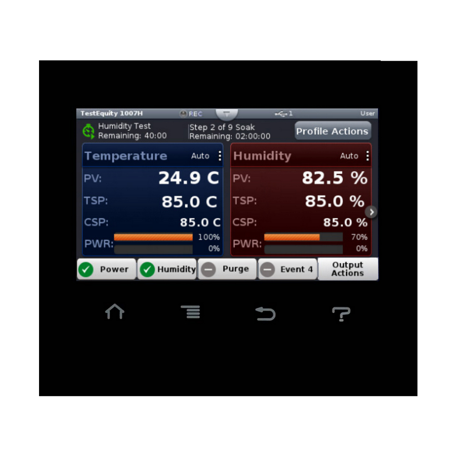
After powering up the controller a white screen will appear first while initializing. Once the startup process is complete the Home Screen will be presented as shown below. The image below shows a configured Home screen for a TestEquity Temperature/Humidity Chamber while it is running a profile. -
Page 9: Home Screen Parameters
• Output Actions: Allows you to monitor the ON/OFF status of controller outputs. Front Panel Navigational Buttons Four buttons at the bottom of the F4T are displayed as icons shown below. The text in this graphic was placed there for clarity only and is not present on the front panel. -
Page 10: Manual Chamber Operation
Set Point is the Temperature or Humidity setting that you want the chamber to maintain. The F4T Controller is in Static Set Point Mode when it is not controlling a Profile. The Static Set Point is entered in the Closed-Loop Set Point screen. -
Page 11: Chamber Functions (Output Widget)
The buttons can be pressed to toggle the functions ON/OFF in manual mode or while a profile is running. The image below shows an F4T with Power, Humidity Purge, and Event 4 in the output widget. Below is a summary of some typical button functions. -
Page 12: Ramp To Set Point
Chapter 2 – Using the F4T Front Panel Ramp to Set Point The F4T can ramp to a set point without having to write a profile. The Ramp settings are located in the Loop Operational Parameter screen. Pressing the vertical ellipsis or anywhere within the outlined box shown below will provide access to the Loop Operational Parameter screen. -
Page 13: Profile Mode
Chapter 2 – Using the F4T Front Panel Profile Mode Profile Actions The profile status bar will appear on the home screen when the controller is powered up. When the Profile Actions button on the Home Screen is clicked, one of three pop-up windows will appear as described below. -
Page 14: Profile Parameters
Chapter 2 – Using the F4T Front Panel Profile Parameters The following settings apply to the entire profile. This screen will appear when Create Profile is pressed or when you edit a profile and View/Edit Details is pressed. Name: User-entered identifier for the profile. The name follows the profile when it is saved in a file or moved to another controller. - Page 15 Chapter 2 – Using the F4T Front Panel Step Type Set the behavior of the step. Step Type options include: Soak: Maintains the temperature or humidity set point constant for the step’s Time. • Hours, Minutes, Seconds (How long the step will hold at this condition) •...
- Page 16 Chapter 2 – Using the F4T Front Panel Jump: Repeats previous steps in the profile starting at the step set with Jump to Step for the Number of Times set. This option is not available for step 1. • Jump Step •...
-
Page 17: Sample Ramp And Soak Profile
9. End with the chamber turned OFF. Entering the above profile from the F4T front panel: • From the Main Page press Profile Actions. • Then press Create Profile on the screen that pops up. This will take you to the New Profile Screen. - Page 18 Chapter 2 – Using the F4T Front Panel • Press Add Step. You will now see Step 5. o Change step type to Soak. o Enter 2 for Hour and 30 for Minutes. o Press Done. • Press Add Step. You will now see Step 6.
-
Page 19: Data Logging
Logged Data Points This menu indicates which data points have been selected. Select Data Points You can select the parameters which get logged. TestEquity has pre-configured the controller to log the Set Point and Process Value. Setup • Logging Status: indicates whether or not recording is active or not. -
Page 20: How To Enable Data Logging
Chapter 2 – Using the F4T Front Panel How to Enable Data Logging There are three ways to initiate data logging: To enable data logging using the front panel: 1. Press the Menu button. 2. Press the Data Logging button. -
Page 21: Transferring Data Log Files
1. Insert a USB thumb drive into USB host port on the chamber. 2. Press the Menu button. 3. Press the File Transfer button. Allow time for the F4T to load the USB thumb drive. After it is loaded, the USB thumb drive name will appear. -
Page 22: Trend Charts
To access trend charts, press the Menu button and then the Trending button. Press the Actions button for Trend Chart 1. This chart has already been set up by TestEquity to display the Temperature Process Value (and Humidity Process Value in humidity chambers) and the respective Set Points. -
Page 23: Exporting/Importing Profiles And Configuration Via Usb
A progress bar will appear and then indicate 100% when done. Transferring Configuration Files The F4T configuration file contains a “System Image” of all settings that determine how the controller inputs and outputs work and how the display appears. The configuration file also contains all profiles. -
Page 24: Personalizing The Home Screen
Chapter 2 – Using the F4T Front Panel Personalizing the Home Screen Placement of objects on the home screen can be modified by the user. You must have a password to enter the Personalization screen. Note: Your controller might not have all the choices available depending on its configuration. -
Page 25: Changing Loop Operational Parameters
You must have a password to change the loop PID tuning parameters. ! CAUTION: The F4T PID tuning values have been properly configured by TestEquity to match the chamber’s system requirements and to perform optimally over a wide range of operating conditions. Improper modifications to these values can result in erratic performance and unreliable operation. -
Page 26: Operations Page
! CAUTION: The Series F4T “Alarm” functions are NOT used in the chamber’s safety system. TestEquity does NOT recommend using the Series F4 alarm function as the main protection device. The independent EZ-Zone Limit Controller functions as the main protection device. -
Page 27: Chapter 3 - Composer Software
Overview Watlow Composer Software can be used to create, edit, and archive profiles. It can also be used to configure the controller. Since the controller is already configured by TestEquity for use in your chamber, configuration instructions are not provided. -
Page 28: Composer Welcome Screen Orientation
It might take a couple of minutes until the controller is found, especially of the F4T is configured for DHCP instead of a fixed IP address. Double clicking on the system will bring up the System Overview screen shown on the next page. -
Page 29: System Overview Screen
• Home, controls access to controller’s home screen.* • Control Mode, controls access to setting the control mode, set points and PID parameters.* • Autotune, controls access to running the autotune feature.* • PID Settings, controls access to the PID settings.* TestEquity F4T Controller Page 29... - Page 30 *This setting limits access to via controller’s front panel user interface only, not via Composer. The image below shows the security levels as configured by TestEquity. You must contact TestEquity to get the passwords for your chamber. After making all of the desired security settings, ensure that the security enabled radio button (top left in the graphic above) is checked.
-
Page 31: Save System Image
2. Use the save as dialog to select the destination folder for the image. 3. Enter the desired filename. 4. Click Save. Note: The system image filename will always have the extension wsi for Watlow System Image and cannot be changed. TestEquity F4T Controller Page 31... -
Page 32: Import System Image
2. Use the open dialog to select the folder location for the previously saved system image. 3. Double-click the desired filename or single-click the filename and then click the Open button. 4. After a system image is imported, we suggest you cycle power to the F4T Controller and restart Composer software. Page 32... -
Page 33: Global Settings
The Pluggable Module screen, located in Device Menus shows what modules are installed. TestEquity has already installed and configured the correct modules for your chamber. Since this is not intended to be an ordinary user function, no further instructions will be covered in this manual. -
Page 34: Personalization
Chapter 3 – Composer Software Personalization ③. This is only viewable if you are logged in as a User or Admin. Located in Device Menus “Personalizing the Home Screen” in Chapter 2 for information on your choices for personalization. Page 34 TestEquity F4T Controller... -
Page 35: Data Logging
Temperature Set Point and Temperature Process Value (the actual chamber temperature) were selected. The chart shown below is only a representation of how the display on the F4T will appear with your choice of settings. Composer software cannot be used to actually plot this data. -
Page 36: Creating And Editing Profiles In Composer Software
Password Protect a Profile: Avoid unwanted and inadvertent changes to a profile with password protection. Changing or Removing a Password from a Profile: When password protection is no longer needed it can be easily removed. Page 36 TestEquity F4T Controller... -
Page 37: Profile View - Screen Orientation
③ Step Detail • Shows all available selections for the selected step while also allowing each to be modified. • You have the ability to give the profile a name as well as apply password protection. TestEquity F4T Controller Page 37... -
Page 38: Profile Parameters
When multiple conditions are specified, the profile will not proceed until all the conditions are satisfied at the same time. • END: Sets the temperature/humidity set points, and event output conditions when the profile ends. See page 16 for more information. Page 38 TestEquity F4T Controller... - Page 39 • On: the step sets the event output on or true. • Off: the step sets the event output off or false. • Unchanged: the step does not set the event output; it remains in whatever state was previously set. TestEquity F4T Controller Page 39...
-
Page 40: Opening The Profile View
Loading a Profile To load a profile previously saved on the computer in to controller memory: 1. Click the Load button. 2. Use the open dialog to locate and select the desired profile file. 3. Click Open. Page 40 TestEquity F4T Controller... -
Page 41: Duplicating A Profile
To insert a new step ahead of an existing step: • Right-click the step and choose Insert Step Before in the pop-up menu. • Click the step and then click the Insert Before button at the bottom of the step list. TestEquity F4T Controller Page 41... -
Page 42: Deleting Steps
6. Click OK. To remove a profile’s password: 1. Select the profile by clicking it in the profile list. 2. Enter the password and click OK. 3. Click the Password button. 4. Click the Remove button. Page 42 TestEquity F4T Controller... -
Page 43: Chapter 4 - Communications
Chapter 4 – Communications Chapter 4 – Communications Ethernet Parameters This section describes how to configure the Ethernet Communications settings in the F4T controller. Changing Ethernet Parameters 1. Press the Menu, Settings and Network buttons, in that order. 2. Under Communications Channels press Ethernet. -
Page 44: Rs-232 Parameters
• Parity: [None] Must match the parity of your computer’s serial port and software. • Display Units: °F, °C [configured by TestEquity for °C] • Modbus Word Order: [High], Low Modbus allows a user to select the word order of two 16-bit words in floating point values. -
Page 45: Modbus
2. Press the Settings button and then the Network button 3. Select the Ethernet (for LAN) or Modbus (for RS-232) communications channel 4. Scroll the screen down to find Data Map and select 1 (for F4T) or 2 (for legacy F4 Compatibility Mode). -
Page 46: Common Modbus Registers
Common Modbus Registers F4T Mode The following registers are applicable in the F4T Mode (Data Map 1). These are the most common registers that would need to be used in an automation environment. Some F4T parameters are contained within 32 bits (IEEE Float). Notice that only one (low order) of the two registers is listed. -
Page 47: F4 Compatibility Mode
F4 Controller. Only a limited set of parameters are available in this compatibility mode, but it should be sufficient for most applications. F4 Compatibility mode is not yet implemented with versions of the F4T that have Cascade Control (part temperature control). -
Page 48: Scpi Programming Mode
The SCPI protocol is only available over Ethernet port 5025. SCPI commands are not yet implemented with versions of the F4T that have Cascade Control (part temperature control). All temperature values for SCPI commands are in °F only. - Page 49 Example :PROGRAM:SELECTED:STEP 1 (set the current profile step to step number 1) :PROGram:SELected:STATe STArt - Start the current profile :PROGram:SELected:STATe PAUSe - Pause the current profile :PROGram:SELected:STATe RESume - Resume the current profile :PROGram:SELected:STATe STOP - Terminate the current profile TestEquity F4T Controller Page 49...
-
Page 50: Gpib And Ethernet Modbus Interface Converters (Optional)
GPIB commands to serial Modbus commands that are transmitted over RS-232. The GPIB Converter also takes care of calculating block checksums that are required for communications to and from the F4T Controller. For more details, see the documentation that came with the GPIB interface option. -
Page 51: Programming Syntax For The F4T Controller, Data Map 1
Chapter 4 – Communications Programming Syntax for the F4T Controller, Data Map 1 The following applies if the F4T serial interface is configured for Data Map 1. This only applies for programming through the GPIB or Ethernet Modbus converters. The F4T Controller uses two consecutive register to control a value or to read back a process variable. -
Page 52: Programming Syntax For The F4T Controller, Data Map 2
WF 2798, value (0 to 99,999) Programming Syntax for the F4T Controller, Data Map 2 The following applies if the F4T serial interface is configured for Data Map 2, F4 Compatibility Mode. See register numbers on the previous page. This only applies for programming through the GPIB or Ethernet Modbus converters. -
Page 53: Chapter 5 - Event Board Option Te-0033
Chapter 5 – Event Board Option TE-0033 Introduction The F4T Controller has several uncommitted outputs which can be used to turn remote devices on and off. Option TE-0033 provides four Solid State Relays that are controlled by Event Outputs in the F4T Controller. -
Page 54: Controlling The Events
ON/OFF in manual mode or while a profile is running. The image below shows an F4T with Power, Humidity Purge, and Event 4 in the output widget. Depending on your chamber configuration, you might see Event 4, 5, and 6 on the output widget. -
Page 55: Chapter 6 - Retransmit Option Te-F4T-Retransmit
When used in a humidity chamber, this option deletes Events 6 and 7. Connections Connections to the Retransmit terminals are on the back of the F4T controller. You will have to open the chamber’s electrical system to access these terminals. -
Page 57: Chapter 7 - F4T Controller Calibration
See F4T diagram on the next page for the terminal locations. For Air Sensor Input Calibration • Remove the wires from terminals R1 and S1 on F4T Slot 1. (R1 is Blue and S2 is Red) • Connect the Precision Millivolt source as follows: + lead to R1 on Module 1 –... -
Page 58: F4T Connections
Chapter 5 – Event Board Option TE-0033 F4T Connections S1 – R1 + T1 + S1 – Page 58 TestEquity F4T Controller...
Need help?
Do you have a question about the F4T and is the answer not in the manual?
Questions and answers