Table of Contents

Subscribe to Our Youtube Channel
Related Manuals for Codan 8571

Summary of Contents for Codan 8571
- Page 1 8570 and 8571 Remote control Operators handbook...
- Page 3 No part of this handbook may be reproduced, transcribed, translated into any language or transmitted in any form whatsoever without the prior written consent of Codan Pty Ltd. © Copyright 1996 Codan Pty Ltd. Codan Part Nº 15-04018 Issue 2, February 1996...
-
Page 5: Table Of Contents
Switching on the transceiver from the console....3-4 Channels .................. 3-5 How to select a channel ............. 3-5 Tuning the antenna ..............3-8 Adjusting the volume............. 3-10 Clarifying the signal .............. 3-11 Muting the background noise ..........3-12 8570 and 8571 Remote control operators handbook... - Page 6 Sending a selective beacon call........4-18 Sending a 99-beacon call ..........4-21 Sending and receiving tone calls ........... 4-23 Sending a tone call............4-24 Receiving a tone call— 8525/8528 series......4-27 Using the free-tuning receiver ..........4-28 8570 and 8571 Remote control operators handbook...
- Page 7 9300 ALE Controller............... 6-6 Sending an ALE call ............6-7 9001 HF Fax and data interface and 9002 data modem... 6-9 Computer ................6-10 Computer command language.......... 6-10 The transceiver responses: ..........6-12 8570 and 8571 Remote control operators handbook...
- Page 8 Contents 7 Appendix Display messages..............7-1 Operator error messages ............ 7-2 System error messages ............7-3 Supply monitor warning messages........7-4 Index Figure Figure 2.1 The 8570 remote control console......2-3 8570 and 8571 Remote control operators handbook...
-
Page 9: About This Handbook
About this handbook The 8570/8571 remote control system is used to control a remotely sited transceiver. This handbook explains how to operate the installed system from the 8570 console. It assumes that you already know how to operate the transceiver and power supply, which are supplied separately. -
Page 10: Standards And Icons
‘ press the Tune button on the remote control console’ • menu names and text requiring emphasis are in italics This icon... Means... the end of a subject. a warning. 8570 and 8571 Remote control operators handbook... -
Page 11: Glossary
Group call a Selcall to all transceivers within a selected group High Frequency Identification Input/output Liquid Crystal Display Light Emitting Diode 8570 and 8571 Remote control operators handbook... - Page 12 Self-ID the programmed address identification number of your station. (Used by other stations to call you.) Selective calling option that transmits to a change- able address; does not decode incoming calls Tcvr Transceiver 8570 and 8571 Remote control operators handbook...
- Page 13 About this handbook Transmit Upper Sideband 8570 and 8571 Remote control operators handbook...
-
Page 14: Other Documents
9001 HF Fax and data interface user guide (Codan part number 15-04038). For information on the installation and operation of the 9002 modem refer to the 9002 HF Data modem user guide (Codan part number 15-04041). For information on using an IPC-500 Radio telephone... -
Page 15: Overview
Overview This chapter describes: • the main features of the 8570 and 8571 remote control system (2-2) • the buttons and knobs that control the 8570 console (2-3) The remote control system is used to control a selected range of Codan high frequency (HF) transceivers. It allows you to install your transceiver in a remote location and control it from another site. -
Page 16: Equipment
Equipment The system consists of two units: • the 8570 remote control console (the console) • the 8571 remote control interface (the interface) The console and interface are connected by a land line or VHF/UHF radio link. You can use most transceiver functions, including channel scanning and selective calling. -
Page 17: The Console
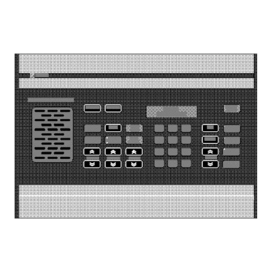
Overview The console Figure 2.1 The 8570 remote control console Key-pad The console has five sets of buttons: • power control • functions • intercom/function • transceiver control • numeric. 8570 and 8571 Remote control operators handbook... -
Page 18: Power Control Buttons
For further information on these options see Setting up the inputs and outputs in the 8570 and 8571 Remote control installation handbook, Chapter 5, Accessories. 8570 and 8571 Remote control operators handbook... -
Page 19: Intercom/Function Buttons
Removes background noise when there is no voice signal present. When mute is selected, the indicator to the top left of the button is on. 8570 and 8571 Remote control operators handbook... - Page 20 Selects the next lower channel. Increases the speaker volume. Decreases the speaker volume. Starts a call on the selected channel. Deletes a channel. Selects the next higher setting. Selects the next lower setting. 8570 and 8571 Remote control operators handbook...
-
Page 21: Numeric Key-Pad
Selects a channel on which to receive or transmit. (Use with 0 button to select a P channel for 8528 only.) Used with number buttons to change the channel number, receive frequency or scan program mode. 8570 and 8571 Remote control operators handbook... - Page 22 Overview 8570 and 8571 Remote control operators handbook...
-
Page 23: Using The System
Using the system This chapter explains how to operate your remote control system. It assumes that the equipment has been installed and setup to operate correctly, as described in the 8570 and 8571 Remote control installation handbook, Chapter 3, Installation. -
Page 24: Operating The Remote Control System
The final message on the display is one of the following: If the remote transceiver is on: C h a n 9 , 9 8 3 . 0 9 , 9 8 3 . 0 8570 and 8571 Remote control operators handbook... - Page 25 3-4. If the remote power supply is off: alternating with In this case you must first switch the power on at the remote location and then on at the transceiver. 8570 and 8571 Remote control operators handbook...
-
Page 26: Switching On The Transceiver From The Console
9 , 9 8 3 . 0 9 , 9 8 3 . 0 The system is ready for use. You must now select a channel on which to receive or transmit, as explained in the next section. 8570 and 8571 Remote control operators handbook... -
Page 27: Channels
These channels are normally programmed when the equipment is supplied, but additional channels can be added by an approved Codan service agent, or where licence permits, by the operator. The licensing restriction only applies to transmit frequencies. - Page 28 If you press the button once the next channel is displayed. If you hold the button down the channels are scrolled on the display. up or down until the channel you want is displayed. 8570 and 8571 Remote control operators handbook...
- Page 29 2 6 4 1 2 , 2 1 7 . 0 C h a n 1 1 , 5 0 1 . 0 P 8 5 1 1 , 5 0 1 . 0 8570 and 8571 Remote control operators handbook...
-
Page 30: Tuning The Antenna
The remote antenna starts to tune. This message displays during the tuning period: The transceiver ‘ beeps’ while the antenna is tuning. When it is tuned two high pitched ‘ beeps’ are heard and this message is displayed: 8570 and 8571 Remote control operators handbook... - Page 31 Notes If no tuning point can be found, 1. cont. two low pitched ‘ beeps’ are heard and this message is displayed: This means that the antenna may be faulty or incorrectly installed. 8570 and 8571 Remote control operators handbook...
-
Page 32: Adjusting The Volume
Adjusting the volume To adjust the speaker volume: Action Notes Press As you adjust the volume, any muting selected momentarily switches off. The transceiver ‘ beeps’ at the minimum and maximum volume settings. 3-10 8570 and 8571 Remote control operators handbook... -
Page 33: Clarifying The Signal
To use the clarifier: Action Notes Press The transceiver ‘ beeps’ at the minimum and maximum settings. (up or down) until the sound quality is improved. 8570 and 8571 Remote control operators handbook 3-11... -
Page 34: Muting The Background Noise
To switch on press The indicator is lit when this option is selected and the display does not change. This control inhibits background To switch off press noise until a selective call is received. 3-12 8570 and 8571 Remote control operators handbook... -
Page 35: Scanning Channels
Your system must include a suitable broadband antenna or Codan automatic antenna tuner for scanning to be successful. Programming scan tables The scan tables and programming procedure differ slightly... - Page 36 (P57 in the example in step 1.) Note: to select P channel enter 0 before the channel number. If necessary, press The light on the USB/LSB button shows the current mode. button to select the required mode. 3-14 8570 and 8571 Remote control operators handbook...
- Page 37 Press to enter. Repeat this procedure for the remaining required channels in the scan table. 8570 and 8571 Remote control operators handbook 3-15...
- Page 38 If you make an error while entering the channels, press then then start setting up the scan table again. Note: When in scan programming mode press Review to step through channels in the scan table. 3-16 8570 and 8571 Remote control operators handbook...
- Page 39 • channel frequency and operating sideband mode. To program scan channels into the transceiver: Action Notes Press The display shows: Scan PROGRAM then Table number 1 within one second to begin the process. 8570 and 8571 Remote control operators handbook 3-17...
- Page 40 Press The display shows: Retrieving Scan table _ _ _ to retrieve the selected scan table. Select scan mode This example shows Selcall mute using selected: Scan Mode Enter Selcall m ute 3-18 8570 and 8571 Remote control operators handbook...
- Page 41 ALE mute Can only be selected if ALE unit is fitted— Scan stops for ALE calls only. Note: Current mute setting is also displayed. Action Notes Press Your selection will be retained. 8570 and 8571 Remote control operators handbook 3-19...
- Page 42 Press to select Sideband (if available). The display shows: Press Scan program enter the selected 12,200.0 channel into the scan table. after the channel is programmed into the scan table. 3-20 8570 and 8571 Remote control operators handbook...
- Page 43 Use the up and down buttons to review channels already programmed into the scan table. Press To exit without saving changes to the scan table press PTT. then within one second to save your changes. 8570 and 8571 Remote control operators handbook 3-21...
-
Page 44: Selecting A Programmed Scan Table
Press Alternatively, press 1, 2 or 3 on the numerical key-pad. up or down to select the required scan table 1, 2 or 3. Press to return to channel mode. 3-22 8570 and 8571 Remote control operators handbook... -
Page 45: Scanning For Incoming Calls
Use Pause scanning if Light on Mute you expect voice calls On/Off button. and want scanning to pause for three seconds when voice is detected on the channel.Scanning also stops for Selcalls. 8570 and 8571 Remote control operators handbook 3-23... - Page 46 Action Notes Press The scan table number is not shown for 8525 and 8528. It is shown for 9323 and 9360: Chan Scanning 1 to commence 5 ,875 .0 scanning selected channels. 3-24 8570 and 8571 Remote control operators handbook...
- Page 47 Press If PTT is used the display shows: P t t n o t a l l o w e d again to stop scan, It will not transmit. or PTT twice. 8570 and 8571 Remote control operators handbook 3-25...
-
Page 48: Using Autoscan
For 9323 and 9360 transceivers only, the autoscan always selects table 1. You enable autoscan using a console setup option— function 1. See 8570 and 8571 Remote control installation handbook, Chapter 6, Setup functions and options for instructions. 3-26 8570 and 8571 Remote control operators handbook... -
Page 49: Viewing The Setup Functions Menus
To return to the normal operating display press Function again (or leave the keys untouched for one minute, after which time the display resets to normal). 8570 and 8571 Remote control operators handbook 3-27... -
Page 50: Functions And Options Available
Group 2 line set up— includes function and option menus specific to the line or link connecting the system equipment. Within each group there are functions that are identified with a number. 3-28 8570 and 8571 Remote control operators handbook... - Page 51 Using the system See the 8570 and 8571 Installation handbook, Chapter 6, Setup functions and options for more information about these functions: Function Description Group 0 Setting a PIN (password) (Console setup General setup options options) Access priority options Set start-up mute...
-
Page 52: Setting Up The Console For Selective Calling
Function and Control On/Off keys are held down the display will show ‘ SECURITY PIN’ . Enter the PIN number and press Enter. See also the 8570 and 8571 Remote control installation handbook, Chapter 6, Setup functions and options: Function 1. - Page 53 To leave the setup mode, switch the menu options. the console off using the On/Off key. Press up or down to change the state of any option. 8570 and 8571 Remote control operators handbook 3-31...
- Page 54 For split site systems all connected transceivers (operating receivers and transmitters) must not be programmed with a Selcall self address ID. See the 8570 and 8571 Installation handbook, Chapter 2, Overview, Selective calling for more information. Example of the display: Refer to Making changes—...
- Page 55 Tone setting is the normal operating mode. Example of the display: GE NE RA L SE TUP Rev ertiv e: ton e Refer to Making changes— selective call on page 3-31 for the procedure for making changes. 8570 and 8571 Remote control operators handbook 3-33...
- Page 56 • ‘ off’ . Example of the display: G EN ER AL S E TUP S 'call Lock: of f Refer to Making changes— selective call on page 3-31 for the procedure for making changes. 3-34 8570 and 8571 Remote control operators handbook...
- Page 57 Example of the display: G EN ER AL S E TUP D igi ts : 4 or 6 Refer to Making changes— selective call on page 3-31 for the procedure for making changes. 8570 and 8571 Remote control operators handbook 3-35...
- Page 58 Using the system 3-36 8570 and 8571 Remote control operators handbook...
-
Page 59: Sending And Receiving Calls
Sending and receiving calls This chapter explains how to send and receive calls. It assumes that the equipment has been installed and setup to operate correctly, as described in the 8570 and 8571 Remote control installation handbook, Chapter 3, Installation. This chapter covers: •... -
Page 60: Sending A Voice Call
Note: Remember to release the PTT button to listen for a response. Hold the micro- phone side-on, close to your mouth, and speak clearly. 8570 and 8571 Remote control operators handbook... -
Page 61: Using The Microphone
• speak clearly at normal volume and rate • use the word ‘ over’ to indicate when you have finished speaking and release the PTT button • your conversation can be monitored by anyone tuned to your transmit frequency. 8570 and 8571 Remote control operators handbook... -
Page 62: Ptt Timer
You set the PTT timer using a general setup option— function 1. See 8570 and 8571 Remote control installation handbook, Chapter 6, Setup functions and options for instructions. 8570 and 8571 Remote control operators handbook... -
Page 63: Selective Calling
Your console must be set up to use the selective calling facility. For information about how to do this, see Chapter 3, Using the system, Setting up the console for selective calling. 8570 and 8571 Remote control operators handbook... -
Page 64: Sending A Selective Call
You will hear background receiver using noise. If your system has Receiver noise may increase. an automatic antenna tuner system, press to tune this channel. Listen. Ensure the selected channel is free of voice or data transmission. 8570 and 8571 Remote control operators handbook... - Page 65 The display shows: C h a n S e n d i n g 2 3 2 2 4 6 to send call. You will hear a ‘ warbling’ sound for approximately ten seconds. 8570 and 8571 Remote control operators handbook...
- Page 66 If the called station is attended, voice communication can commence. If unattended, your call will be recorded in the call stack at the called station for later communications. 8570 and 8571 Remote control operators handbook...
-
Page 67: Receiving A Selective Call
Pressing PTT on the called channel removes the ‘ Cald’ and ID from the display. The called ID remains in the call stack. Pressing Delete will delete entries from the call stack when you are reviewing calls. 8570 and 8571 Remote control operators handbook... -
Page 68: Receiving A Selective Call In Scan Mode
Reviewing received calls on page 4-11). The ‘ pips’ can be stopped by operating any button function. See also Receiving a selective call on page 4-9. See Chapter 3, Programming scan tables for instructions for programming the channels. 4-10 8570 and 8571 Remote control operators handbook... -
Page 69: Reviewing Received Calls
1 3 2 4 To n e c a l l To review the calls, press the Review buttons. Each entry includes the channel on which the call was received. 8570 and 8571 Remote control operators handbook 4-11... - Page 70 3 4 2 2 c a l l e d to select the call you wish to send. Press twice This will send a Selcall to the station that called you using the same channel and call ID. 4-12 8570 and 8571 Remote control operators handbook...
- Page 71 The display shows: C h a n r e v i e w 1 3 2 4 To n e c a l l to select the call to be returned. Press once 8570 and 8571 Remote control operators handbook 4-13...
-
Page 72: Group Calls
00. For example, a call to station 0200 is received by all stations whose identification address is in the range from 0201 to 0299. No revertive will be heard. 4-14 8570 and 8571 Remote control operators handbook... -
Page 73: State Calls And All Calls
Each transceiver must be programmed to respond to either a State call or an All call. A special functions menu (function 2) is used to select the option at the console. See 8570 and 8571 Remote control installation handbook, Chapter 6, Setup functions and options for instructions. - Page 74 A L L to send the State or All call. The type of call sent depends on how your software is set and is indicated on the display when you send the call. 4-16 8570 and 8571 Remote control operators handbook...
-
Page 75: Using The Beacon Feature
Normal selective operation is not affected. Note: If you have an 8525/8528 transceiver with software earlier than version 3.50, you have to send a 99-beacon call. See Sending a 99-beacon call on page 21. 8570 and 8571 Remote control operators handbook 4-17... -
Page 76: Sending A Selective Beacon Call
3 , 8 0 0 . 0 or PTT to stop scanning. Press The display shows: C h a n S e n d ca l l 1 2 2 5 6 3 4-18 8570 and 8571 Remote control operators handbook... - Page 77 1 4 4 4 6 6 to send beacon. Listen for the If the receiving station has an revertive of four automatic antenna tuning system it long tones. will tune the antenna before transmitting the revertive. 8570 and 8571 Remote control operators handbook 4-19...
- Page 78 The transceiver returns to channel mode after the selective beacon call has been completed. C h a n 3 , 8 0 0 . 0 3 , 8 0 0 . 0 4-20 8570 and 8571 Remote control operators handbook...
-
Page 79: Sending A 99-Beacon Call
Before you can make a 99-beacon call, ensure the following has been set up: • the station you are calling is set up for 99-beacon calls • your self-ID (refer to the 8570 and 8571 remote control installation handbook, Chapter 6, Setup functions and options: Function 1) •... - Page 80 C h a n B e a c o n 3 5 9 9 buttons with 99 as the last two digits Press again to send the call. 4-22 8570 and 8571 Remote control operators handbook...
-
Page 81: Sending And Receiving Tone Calls
The calling party is not identified. The TE option only operates on channels programmed with either T1, T2, T3 or T4. See Chapter 5, Programming Channels for instructions. 8570 and 8571 Remote control operators handbook 4-23... -
Page 82: Sending A Tone Call
Press The display shows: C h a n S e n d c a l l 5 , 8 8 0 . 0 4-24 8570 and 8571 Remote control operators handbook... - Page 83 C h a n S e n d i n g To n e c a l l 1 and hold for approximately 10 and a tone is heard during the transmission. seconds. 8570 and 8571 Remote control operators handbook 4-25...
- Page 84 Press The display shows: C h an S en d in g To ne cal l and hold for approximately 10 and a tone is heard during the transmission. seconds. 4-26 8570 and 8571 Remote control operators handbook...
-
Page 85: Receiving A Tone Call- 8525/8528 Series
To cancel the pips and answer the call, press the microphone's PTT button. The tone call appears in the call memory stack. You can review it or delete the call, following the procedure in Reviewing received calls on page 4–11. 8570 and 8571 Remote control operators handbook 4-27... -
Page 86: Using The Free-Tuning Receiver
Sending and receiving calls Using the free-tuning receiver The console can be used to operate Codan transceivers as free-tuning receivers. You can then receive signals or broadcasts within the frequency range of 250 KHz to 30 MHz. The channel created is temporary and is lost when you change channels or turn off the console. - Page 87 1 7 , 5 3 5 . 0 Release The display will remain at the frequency shown when Enter was released. when you end free tuning. To return to the original channel selection press Channel up or down. 8570 and 8571 Remote control operators handbook 4-29...
-
Page 88: Using The Console As An Intercom- Basic Single Site, Split Site Or Daisy Chain
Each console is allocated an intercom number during installation (for more information refer to the 8570 and 8571 Remote control installation handbook, Chapter 6, Setup functions and options, General setup options— function 1). You can call an individual console by ‘... -
Page 89: Example— Operator 1 Calling Operator 2
This example shows you (operator 1) how to use the intercom to call a single operator (operator 2): Action: Operator 1's display shows: Operator 2's display shows: Press followed by: followed by: Press Press Press The console beeps. 8570 and 8571 Remote control operators handbook 4-31... - Page 90 The console emits a series of The console emits a series of beeps. beeps. If connection is made, press PTT and speak. To end, press: Display returns to normal Display returns to normal transceiver mode. transceiver mode. 4-32 8570 and 8571 Remote control operators handbook...
-
Page 91: Example- Operator 1 Calling All Operators
Action: Operator 1's display shows: Other operator (example shown is 2) displays show: Press followed by: followed by: Press Press Press The console beeps. 8570 and 8571 Remote control operators handbook 4-33... - Page 92 While you are talking, a message to this effect is displayed. All other consoles display a message identifying the number of the operator who is talking. If you try to talk while another operator is talking, the following message is displayed: 4-34 8570 and 8571 Remote control operators handbook...
- Page 93 Re-enter a party line The same series of connection messages are displayed as when starting the party line. This enters the party line but does not inform the other consoles. 8570 and 8571 Remote control operators handbook 4-35...
-
Page 94: Receiving Emergency Selcalls
(‘ siren’ ) alarm at the caller’ s console. It is assumed that during installation the Emergency mode of function 1 (see the 8570 and 8571 Remote control installation handbook, Chapter 6, Setup functions and options) has been selected to receive Emergency Selcalls and—... -
Page 95: Programming Channels
This chapter explains how to program channels in your remote control system. It assumes that the equipment has been installed and setup to operate correctly, as described in the 8570 and 8571 Remote control installation handbook, Chapter 3, Installation. This chapter covers: •... -
Page 96: Programming Transceivers Type 8525 And 8528
(3) on the microprocessor PCB (08-03741) of the transceiver before you can program, replace, or delete P-channels. This is an installation operation: refer to the technical service manual 15-02036 for details. 8570 and 8571 Remote control operators handbook... -
Page 97: Copying Channels To A P-Channel- 8525 And 8528
1 2 , 2 1 7 . 0 Press The display shows: E n t r o p t i o n s 2 6 4 S _ , _ U to display the option fields. 8570 and 8571 Remote control operators handbook... - Page 98 Enter the channel The display shows: number. E n t r 1 2 , 2 1 7 . 0 P 8 5 1 2 , 2 1 7 . 0 8570 and 8571 Remote control operators handbook...
- Page 99 Channel buttons. Note: Two-frequency simplex channels (those in which the Rx and Tx frequencies are different) must only use channel reference P70 to P99. 8570 and 8571 Remote control operators handbook...
-
Page 100: Creating A Receive-Only P-Channel- 8525 And 8528
1 2 , 2 1 7 , 0 Press The display shows: E n t r i n h i b i t 2 6 4 _ _ , _ _ _ , _ to begin to program the channel. 8570 and 8571 Remote control operators handbook... - Page 101 Enter the channel The display shows: number (1 to 99), e.g. 42. E n t r i n h i b i t P 4 2 1 2 , 4 5 7 , 5 8570 and 8571 Remote control operators handbook...
- Page 102 The channel remains selected until you change it by pressing one of the Channel buttons. When you scroll through the channels you will see the receive-only channel included, with the Tx frequency inhibited, as shown previously in step 8. 8570 and 8571 Remote control operators handbook...
-
Page 103: Overwriting An Existing P-Channel- 8525 And 8528
Enter the channel The display shows: number e.g. 85. E n t r i n h i b i t P 8 5 11 , 5 0 1 . 0 8570 and 8571 Remote control operators handbook... - Page 104 Channel buttons. Note: Two-frequency simplex channels (those in which the Rx and Tx frequencies differ) must only use channel reference P70 to P99. 5-10 8570 and 8571 Remote control operators handbook...
-
Page 105: Creating A Temporary Channel- 8525 And 8528
The channel is shown without a ‘ P’ number: Note: The example above is a receive-only channel, but you can create temporary channels for both receiving and transmitting. 8570 and 8571 Remote control operators handbook 5-11... -
Page 106: Preventing Accidental Changes Or Deletion- 8525 And 8528
P-channel inhibit menu. Press up or down to scroll The display shows: through the options until the display A CC ES S PR IORITY Al l P ch an in hib reads: 5-12 8570 and 8571 Remote control operators handbook... - Page 107 There are several functions related to P-channels. You can, for example, remove the protection set up. You can also prevent anyone from creating channels. See 8570 and 8571 Remote control installation handbook, Chapter 6, Setup functions and options for more information on these functions.
-
Page 108: Deleting A P-Channel- 8525 And 8528
11 , 5 0 1 . 0 Press The display shows: E n t r o p t i o n s P 8 5 S _ , _ U to display option fields. 5-14 8570 and 8571 Remote control operators handbook... -
Page 109: Press The Display Shows
_ , _ _ _ . _ P 5 7 3 , 8 6 0 . 0 to delete the channel. The channel is now deleted and the channel immediately before it is displayed. 8570 and 8571 Remote control operators handbook 5-15... -
Page 110: Programming Transceivers Type 9323 And 9360
• Upper Sideband mode (USB) or Lower Sideband mode (LSB) • Protected/Not protected Programmed channels that are protected can only be deleted by an approved Codan service agent. Unprotected channels can be deleted at any time. 5-16 8570 and 8571 Remote control operators handbook... -
Page 111: Creating A Receive-Only Channel- 9323 And 9360
The display shows: E n t r i n h i b i t 2 6 4 _ _ , _ _ _ , _ to begin programming the channel— selects Tx inhibit. 8570 and 8571 Remote control operators handbook 5-17... - Page 112 T1 , S_ , _ U , N P Flashing up or down to move to Sideband select. Press Upper sideband Lower sideband UL Upper and Lower sidebands up or down to select sideband. 5-18 8570 and 8571 Remote control operators handbook...
-
Page 113: Number (1 To 99)
The display shows: number (any unused channel) from 1 to E n t r i n h i b i t 9999. _ 1 0 0 1 2 , 4 6 7 . 5 8570 and 8571 Remote control operators handbook 5-19... -
Page 114: E N T R T X I N H I B I T
Programming channels Action Notes Press The display shows: E n t r i n h i b i t 1 0 0 1 2 , 4 6 7 . 5 to complete programming. 5-20 8570 and 8571 Remote control operators handbook... -
Page 115: Copying A Channel And Changing Options On Protected Channels- 9323 And 9360
The display shows: o p t i o n t o n e E n t r _ _ , S _ , _ U , N P to display option Flashing fields. 8570 and 8571 Remote control operators handbook 5-21... - Page 116 S l c l T 1 , S _ , _ U , N P Flashing up or down to move to the next option. Press up or down to select the Selcall option On/Off. 5-22 8570 and 8571 Remote control operators handbook...
- Page 117 E n t r o p t i o n p r o t T 1 , S _ , _ U , N P Flashing up or down to move to the next option. 8570 and 8571 Remote control operators handbook 5-23...
- Page 118 Press The display shows: E n t r 1 2 , 2 1 7 . 0 1 0 0 1 2 , 2 1 7 . 0 to complete programming. 5-24 8570 and 8571 Remote control operators handbook...
-
Page 119: Deleting A Channel- 9323 And 9360
Press The display shows: E n t r 1 2 , 2 1 7 . 0 _ _ _ _ 1 2 , 2 1 7 . 0 8570 and 8571 Remote control operators handbook 5-25... - Page 120 The channel is now deleted and the next lower channel is displayed. Note: You cannot delete a protected channel. Protected channels can only be deleted by Codan or a Service Agent. 5-26 8570 and 8571 Remote control operators handbook...
- Page 121 These are: • IPC-500 Radio telephone interconnect (6-2) • 8580 Data modem (6-3) • 9300 ALE controller (6-6) • 9001 HF Fax and data interface (6-9) • 9002 Data modem (6-9) • Computer (6-10). 8570 and 8571 Remote control operators handbook...
-
Page 122: Ancillary Equipment
Installation manual and the appropriate transceiver handbook. For more information about using the IPC-500 with the remote control system refer to the 8570 and 8571 Remote control installation handbook, Chapter 4, Ancillary equipment. 8570 and 8571 Remote control operators handbook... -
Page 123: 8580 Data Modem
You can use the remote control system with an 8580 modem to transfer serial data between the console and an interface. For information about setting up the remote control system for data transmission, refer to the 8570 and 8571 Remote control installation handbook, Chapter 4, Ancillary equipment. -
Page 124: Receiving An Arq Call
The received call is added to the call memory. See Chapter 4, Sending and receiving calls, Reviewing received calls, for instructions on how to review this list. 8570 and 8571 Remote control operators handbook... -
Page 125: Ending Data Transfer Mode
Once the consoles have received this instruction, the LED on the F2 button goes out and the consoles return to normal operation. 8570 and 8571 Remote control operators handbook... -
Page 126: 9300 Ale Controller
(Codan part number 15-04046). Before you can send an ALE call, you need to: • connect an ALE controller and set the correct RS-232 and baud rate settings (refer to the 8570 and 8571 Remote control installation handbook, Chapter 5, Accessories, RS-232/I C Interface) •... -
Page 127: Sending An Ale Call
S e n d i n g A L E 1 2 3 4 5 6 initiate an ALE call. Note: until Call is pressed for the second time the channels will still be scanned. 8570 and 8571 Remote control operators handbook... - Page 128 (if it is different to that displayed). Press C h a n S e n d i n g A L E 1 2 3 4 5 6 initiate an ALE call. 8570 and 8571 Remote control operators handbook...
-
Page 129: 9001 Hf Fax And Data Interface And 9002 Data Modem
For operation of the 9001 interface refer to the 9001 HF Fax and data interface user guide and for the 9002 refer to the 9002 HF Data modem user guide. 8570 and 8571 Remote control operators handbook... -
Page 130: Computer
RS-232 terminal input of the console. The RS-232 port must be set up as detailed RS-232 terminal menu— function 30, in the 8570 and 8571 Remote control installation handbook, Chapter 6, Setup functions and options. Set the RS-232 to the... - Page 131 (1,2 or 3). (9323/9360 only). MUTE=OFF Sets the mute for the transceiver. MUTE=SELCALL MUTE=VOICE MUTE? Reports the current status as OFF, SELCALL or VOICE. SELCALL=<Selcall ID> Sends a normal Selcall on the current channel. 8570 and 8571 Remote control operators handbook 6-11...
-
Page 132: The Transceiver Responses
Scanning is aborted. SCAN: <number> Scan mode was changed on the control panel. MUTE: OFF Mute mode has been changed by an action MUTE: SELCALL on the control panel. MUTE: VOICE 6-12 8570 and 8571 Remote control operators handbook... - Page 133 If a page call is sent to a transceiver that has a computer and printer connected to its RS-232 port, the following message is printed: PAGE-CALL: <Channel#>, <Selcall ID>, “The received message text” 8570 and 8571 Remote control operators handbook 6-13...
- Page 134 Ancillary equipment 6-14 8570 and 8571 Remote control operators handbook...
-
Page 135: Appendix
If a transceiver fault is indicated the transceiver must be switched off and tried again. If the fault re-occurs the transceiver must be sent to Codan, or a Codan agent, to have the fault rectified. Messages are displayed for five seconds and then normal operation is resumed. -
Page 136: Operator Error Messages
PTT cutout Four The microphone PTT has been active for a longer time than that set in the timer. 8570 and 8571 Remote control operators handbook... -
Page 137: System Error Messages
The external tuner has not completed a tune operation within two minutes. No remote There has been a failure associated with the line/link between the 8570/8571 and the 8570 has entered standby mode. 8570 and 8571 Remote control operators handbook... -
Page 138: Supply Monitor Warning Messages
To preserve battery life and prevent erratic performance, the console can switch off automatically. The following table summarises the events that will occur under specific conditions: 8570 and 8571 Remote control operators handbook... - Page 139 4. Three ‘ beeps’ are given and the message ‘ Warning supply voltage very low’ is displayed. 5. The console switches itself off in 10 minutes. 6. The console switches itself off in 30 seconds. 7. The console switch-off sequence is aborted. 8570 and 8571 Remote control operators handbook...
- Page 140 For split site systems (separate transmitter and receiver) the word ‘ Remote’ in the above messages is replaced by 'Transmit' for the transmitter site, ‘ Receive’ for the receiver site, and ‘ Arbitrate’ for the master 8571 in the star configuration. 8570 and 8571 Remote control operators handbook...
Need help?
Do you have a question about the 8571 and is the answer not in the manual?
Questions and answers