Table of Contents
Advertisement
75V
Softener Manual
1. Page 22 of this manual contains important maintenance procedures for the continued proper
operation of your unit. These MUST be performed regularly for your warranty to remain valid.
2. Read all instructions carefully before operation.
3. Avoid pinched o-rings during installation by applying NSF certified lubricant to all seals (provided with install kit).
4. This system is not intended for treating water that is microbiologically unsafe or of unknown quality without
adequate disinfection before or after the system.
Canada West
Canada East
855 Park St., Unit 1
490 Pinebush Rd., Unit 1
Regina, SK S4N 6M1
Cambridge, ON N1T 0A5
U.S.A.
56 Lightcap Rd.
9760 Mayflower Park Drive,
Pottstown, PA 19464
Suite 110
Carmel, IN 46032
4655 McDowell Rd. W
Phoenix, AZ 85035
Advertisement
Table of Contents

Summary of Contents for Petwa 75V
- Page 1 Softener Manual 1. Page 22 of this manual contains important maintenance procedures for the continued proper operation of your unit. These MUST be performed regularly for your warranty to remain valid. 2. Read all instructions carefully before operation. 3. Avoid pinched o-rings during installation by applying NSF certified lubricant to all seals (provided with install kit). 4.
-
Page 2: Table Of Contents
READ THIS PAGE FIRST BEFORE STARTING INSTALLATION HOW YOUR WATER CONDITIONER WORKS SPECIFICATIONS SPECIFICATIONS SYSTEM DIMENSIONS BRINE TANK DIMENSIONS INSTALLATION UNPACKING / INSPECTION OF TWIN TANK MODEL UNPACKING / INSPECTION OF CABINET MODEL CHECK VALVE TYPE AND VALVE SERIAL # BEFORE INSTALLATION PREPARATIONS INSTALLING BRINE TANK... -
Page 3: Read This Page First
READ THIS PAGE FIRST BEFORE STARTING INSTALLATION Read this manual thoroughly to become familiar with the Avoid pinched o-rings during installation by applying device and its capabilities before installing or operating your (provided with install kit) NSF certified lubricant to all seals. Water Filter. -
Page 4: How Your Water Conditioner Works
HOW YOUR WATER CONDITIONER WORKS Water softeners remove hardness in the water by exchanging particles in the water, or ions. They remove hard ions such as calcium and magnesium in the water by trading it for sodium ions producing soft water. Unlike the calcium and magnesium, sodium stays dissolved in water and does not form a scale. Sodium also does not interfere with the cleaning action of soaps. -
Page 5: Specifications
SPECIFICATIONS System Capacity Grains Flow Rate Regeneration Water Usage Mineral Resin Brine Tank / Cabinet Size Salt Capacity Ship Weight Model Service Backwash @ 6 Lbs/Cu Ft Factory Setting Tank Size Cu. Ft. Inches (Lbs) (Lbs) @ 10 Lbs/Cu ft (Factory Setting) @ 3 Lbs/Cu Ft USGPM USGPM... -
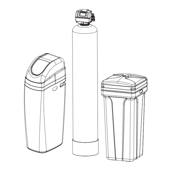
Page 6: System Dimensions
SYSTEM DIMENSIONS Twin Tank Model PW75V-75 44” 8” PW75V-100 48” 9” PW75V-150 54” 10” PW75V-200 52” 12” PW75V-250 54” 13” PW75V-300 65” 14” PW75V-75C 35” 9” PW75V-100C 35” 10” Cabinet Model... -
Page 7: Brine Tank Dimensions
BRINE TANK DIMENSIONS Model Color Liquid Volume Tank Dimensions 5 Pack Carton Salt Capacity 5 Pack Carton (inches) Dimensions (inches) Shipping Weight US Gal Liters L x W x H L x W x H Brine Tanks BTR-70 Black 20.3 76.5 15.8 x 32.1 16.7 x 16.7 x 61.0... - Page 8 BTR70 BTR100 BTR145 BTR200 salt tank lid salt tank body brine well and brine valve salt grid system salt grid system BTR 200l label (7.3") (20.35")
-
Page 9: Unpacking / Inspection Of Twin Tank Model
UNPACKING / INSPECTION OF TWIN TANK MODEL Be sure to check the entire unit for any shipping damage or parts loss. Also note damage to the shipping cartons. Contact the transportation company for all damage and loss claims. The manufacturer is not responsible for damages in transit. Small parts, needed to install the Softener, are in a parts box. - Page 10 For Model 250 and 300 the media and Control Valve is packaged separately in carton and bags What is included with 300 model? There are 6 Red clips. Please check to 2. Control Valve make sure you have all of them. 1.
-
Page 11: Unpacking / Inspection Of Cabinet Model
UNPACKING / INSPECTION OF CABINET MODEL 1. Cabinet with Valve attached 2. Parts Box 3. Drain Line and Hose Clamp (Not Included with some models)) 2. Parts Box Bypass Tool 2 X 3/4” Elbow Adapter) Grease Packet 2X 1” Straight Adapter Transformer... -
Page 12: Check Valve Type And Valve Serial
CHECK VALVE TYPE AND VALVE SERIAL # Check to make sure Valve Type is Upflow (UF) (left Sticker shown below). The right Sticker shows the serial # of the control valve. The middle Sticker is dataplate which provides information of Serial # and Date of Manufacture of complete system. Both Serial # labels are important for troubleshooting. Please record these numbers for future use on page 23 in the maintenance section. -
Page 13: Before Installation
BEFORE INSTALLATION NOTE Make sure you have a copy of your most recent water test results. If your water has not been tested previously you can contact All government codes and your supplier of this product to obtain a water sample bottle to be sent to one of our facilities for a free analysis. It is important regulations governing the that this product not be installed until you have this information. -
Page 14: Preparations
CAUTION! PREPARATIONS The unit should be 1. Media Installation (When Necessary). Models including and higher than 2 CF (Models 250,300) of media are shipped with depressurized before separate media in pails or boxes. Models lower than 2 CF of media come loaded with media and this step can be skipped for new installing or replacing media installation. - Page 15 PREPARATIONS Determine the best location for your water softener, bearing in mind the location of your water supply lines, drain line and 120 volt AC electrical outlet. Subjecting the softener to freezing or temperatures above 43°C (110°F) will void the warranty. Please notice the inlet and outlet labels on the valve as shown here to determine the position of the equipment: Inlet...
-
Page 16: Installing Brine Tank
INSTALLING BRINE TANK a) Attach the three brine grid legs to grid plate. The c) Drop the brine grid with brine well inside the d) Take the brine tube and insert the nut and plastic sleeve as legs will snap on to the tabs of the salt plate making brine tank such that the nut fitting faces the shown below. -
Page 17: Water Softener Installation
WATER SOFTENER INSTALLATION Connect Softener to the HousePlumbing Any solder joints near the valve must be done before connecting any piping to the valve. Always leave at least 6” (152 mm) between the valve and joints when soldering pipes that are connected to the valve. Failure to do this could cause damage to the valve. Water Softener Installation Cold (Raw water) Cold (Raw water) -
Page 18: Cabinet Water Softener Installation
CABINET WATER SOFTENER INSTALLATION Cold (Raw water) Cold (Raw water) Cold (Filtered water) To Outside Faucet In Out Cold (Soft Water) Filter Hot (Soft Water) Water Heater Up ow Water Softener Inlet Water Pipe Outlet Outlet Water Pipe Inlet NOTICE - THERE ARE INLET AND OUTLET LABELS ON THE VALVE. -
Page 19: Startup Instructions
STARTUP INSTRUCTIONS 3. Screen Display 1. Connect the Transformer to the Valve Familiarize with Button Configuration: Plug the 12-volt transformer into a 120 VAC 60 Hz outlet. JAN/01/2018 12:00AM DAYS REMAINING: 2 The controller will show the following on the screen - Time, Date and number of Days Remaining for Regeneration. - Page 20 STARTUP INSTRUCTIONS (CONTINUED) 4. Manually Regenerate the Valve (Continued) 4a. Open the inlet on the bypass valve slowly and allow water to enter the unit. (The outlet of the bypass should remain closed to prevent any fines or debris from entering the plumbing system.
-
Page 21: Maintenance Instructions And Schedule
MAINTENANCE INSTRUCTIONS AND SCHEDULE System Check List NOTE** All units are factory programmed for the correct size and regeneration cycle alteration should only be done by a factory trained technician or after consultation with one of our technical representatives if you have any questions please call: 877-288-9888 4a. -
Page 22: Important Warranty And Maintenance Information
MAINTENANCE INSTRUCTIONS AND SCHEDULE Checking the Salt Level Check the salt level monthly. Remove the lid from the cabinet or brine tank, make sure salt level is always above the brine level. CAUTION! Add Salt to the Brine Tank Put 40 kgs of crystal water softener salt in the brine tank. The unit will automatically fill the water to the correct level when it Incorrect start up, water regenerates. -
Page 23: Care Of Your Softener
Care of Your Softener To retain the attractive appearance of your new water softener, clean occasionally with a mild soap solution. Do not use abrasive cleaners, ammonia or solvents. Never subject your softener to freezing or to temperatures above 43°C (110°F). Servicing Components Ÿ The injector assembly should be cleaned or replaced every year depending on the inlet water quality and water usage. - Page 24 Res-Up® Feeder Installation Instructions Round Brine Tank - continued 4. IInstall the holder and the Res Care Solution 5. Take off the small hole cover on the Brine Well lid. 6. Take off the cover of the Res care bottle . Insert the wick, making sure it touches the bottom of the bottle.
-
Page 25: Servicing 75 Valve
Install Resup Feeder -Square Brine Tank - continued 4. IInstall the holder and the Res Care Solution 5. Take off the small hole cover on the Brine Well lid. 6. Take off the cover of the Res care bottle . Insert the wick, making sure it touches the bottom of the bottle. -
Page 26: Replacement
POWERHEAD REPLACEMENT Remove 2 screws Remove front cover Remove 4 screws Remove 7 body Remove cam screws assembly Remove pin Remove Idler gear 1. Remove front cover 4. Remove pin 7. Remove 4 screws 2. Remove 2 screws shown 5. Remove 7 body screws 8. -
Page 27: Meter Assembly Replacement / Clean Injector Assembly
METER ASSEMBLY REPLACEMENT 1. Disconnect the valve from bypass by removing clips 3. Remove the meter support and then the impeller out from the coupling and 2. Remove the coupling adapter from the valve clean it 4. Replace meter and re-assemble the removed components back in the section CLEAN INJECTOR ASSEMBLY 1. -
Page 28: Replacing The Bypass And Meter Cable
Valve Model Region supply back into unlock the screen. the wall socket Press and hold the Up and Down Arrows. 75V Series U.S Gallon 0.576 0.443 and follow the Press the down arrow to get to METER RATIO then press SET. -
Page 29: Replace Motor /Replace Drain Line Flow Control / Replacing Pcbs
REPLACE MOTOR Remove front cover 1. Remove front cover 4. Remove 6 screws 2. Remove Pin 5. Remove plate 3. Remove Gear 6. Replace motor REPLACE DRAIN LINE FLOW CONTROL Clip 1. Pull the drain line clip and remove the drain line elbow and washer 2. -
Page 30: After Servicing
AFTER SERVICING 1. Reconnect drain line 2. Return bypass or inlet valve to normal in service position. Water Pressure will automatically build in the Softener NOTE Be sure to shut off any bypass line. 3. Check for leaks at all sealed areas. Check Drain seal with the control in the backwash position 4. - Page 31 PARTS BREAKDOWN Powerhead Parts List Part # Description 60010331 Power Cable Clip 60010330 Meter Cable Clip 60010124 Power Cable Micro Switch Cable 60010266 Meter Cable 60095635 Plastic Screw M5×70 60095613 Plastic Screw M5×30 60095615 75 Valve Base(Black) 60010075 Screw M5×12 60095636 Pressing Block 60095634...
-
Page 32: Valve Body
PARTS BREAKDOWN Piston Assembly 92398 Valve Body Parts List Part # Description 13446 End Plug Assy 60095604 BNT 75 Piston Rod 60010646 Piston Retainer 60010647 60010648 Piston 60010130 Seal & Spacer Kit BNT 75 Valve Body 60095609 60010095 Air Dispenser Seal and Spacer Kit 60010096 O-ring(11×2) - Page 33 PARTS BREAKDOWN PARTS BREAKDOWN Bypass Parts List Part # Part # Description (Water Group) (Canature) 60010267 05010108 Grey Meter Cable cc 60010006 70020007M Bypass Tool 05056212 063 Bypass Body 60010026 26010143 O-ring on Inlet and Outlet 60010019 21319011N Straight 1" NPT Inlet and Outlet 60010023 21319036N Elbow 3/4"...
-
Page 34: Cabinet
PARTS BREAKDOWN Cabinet Parts List Part # Description Part # Description 25010028 Pressure Tank-935 Transparent Plate Holder-Right 1 25010043 Pressure Tank-1035 60010673 Screw 2.9×10 50010020 Distribution Assy-1035 Softener Salt Lid 50010001 Top Cone Hoop Clinch 10010038 Control Valve Assy Plastic Screw Softener Cabinet(Grey) Brine Well Clamp Softener Low Cover(Black) -
Page 35: How To Set Date And Time, Manual Regeneration And Dealer Information
HOW TO SET DATE AND TIME, MANUAL REGENERATION AND DEALER INFORMATION PRESS “MENU” KEY AND SCROLL TO “MAIN MENU”. THEN PRESS “SET” TILL IT BEEPS. Press “MENU” key to change menu option. Press “SET” Press to enter. Press to change value. Press “SET” to accept. -
Page 36: Main Menu
MAIN MENU Press “MENU” key . Press - to advance to Menu. Press and hold “SET” 5 seconds or until you hear a beep. Press to choose menu option. Press “SET” to enter. Press to change option. Press SET” to accept. REGEN TIME Date and Time This setting determines the time of day to perform a scheduled... -
Page 37: Master Programming
MASTER PROGRAMMING The controller will show the following on the screen - Time, Date and number How to set Master of Days Remaining for Regeneration: Programming (Authorized Dealer Only) JAN/01/2018 12:00AM Press for 8 seconds. Press “SET” DAYS REMAINING: 2 to select and “MENU”... - Page 38 75V, 750 DOWNFLOW SOFTENER PROGRAMMING Steps MODEL Softener Softener Softener Softener Softener Softener Softener Softener Size 100C RESIN VOLUME 0.75CF 1.0CF 0.75CF 1.0CF 1.5CF 2.0 CF 2.5 CF 3.0 CF LANGUAGE ENGLISH REGION GALLONS VALVE SETUP DownFlow METER RATIO AFTER 4.428...
- Page 39 Steps MODEL Softener Softener Softener Softener Softener Softener Softener Softener Size 100C RESIN VOLUME 0.75CF 1.0CF 0.75CF 1.0CF 1.5CF 2.0 CF 2.50 CF 3.0 CF LANGUAGE ENGLISH REGION US GALLONS VALVE SETUP DownFlow METER RATIO AFTER 4.428 PRESS ‘+’ AND ‘ _ ’ MAR 20,2018 FOR 5 SECONDS METER RATIO BEFORE...
- Page 40 Toll Free: 1-877-288-9888 • • • • Regina, SK Cambridge, ON Carmel, IN Pottstown, PA Phoenix, AZ 54672 09/18...
Need help?
Do you have a question about the 75V and is the answer not in the manual?
Questions and answers