Table of Contents
Advertisement
Electro-Hydraulic Tire Changer
For Medium and Large Size Tires
CHD-9551
OPERATING AND MAINTENANCE INSTRUCTIONS
READ these instructions before placing unit in service KEEP
these and other materials delivered with the unit in a binder
near the machine for ease of reference by supervisors and
operators.
85010081/01
Revision 03/18
Advertisement
Table of Contents

Summary of Contents for Coats CHD-9551
- Page 1 Electro-Hydraulic Tire Changer For Medium and Large Size Tires CHD-9551 OPERATING AND MAINTENANCE INSTRUCTIONS READ these instructions before placing unit in service KEEP these and other materials delivered with the unit in a binder near the machine for ease of reference by supervisors and operators.
-
Page 2: Table Of Contents
INDEX 1 - GENERAL INFORMATION....................................3 2 - TECHNICAL DATA......................................3 3 - GENERAL SAFETY REGULATION..................................3 4 - SAFETY DEVICES......................................3 5 - TRANSPORT........................................3 6 - UNPACKING........................................4 7 - INSTALLATION........................................4 7.1 Installation place ............................................4 7.2 Workplace requirements...........................................4 7.3 Electric hook up............................................6 Sense of rotation check 8 - LAYOUT OF FUNCTIONAL PARTS...................................7 9 - IDENTIFYING WARNING SIGNALS.................................8 10 - IDENTIFICATION OF CONTROL..................................9... -
Page 3: General Information
GENERAL INFORMATION This tyre changer has been specifically designed to demount and mount truck, bus and commercial van tyres, with rims from 14" to 56" and a maximum 2.400 mm diameter. Any other use is improper and therefore not authorized. Before beginning any kind of work on or with this machine, carefully read and understand the contents of these operating instructions. -
Page 4: Unpacking
lbs 2745 (KG. 1245) UNPACKING Once the packing material has been removed, check the machine visually for any signs of damage. Keep the packing materials out of the reach of children as they can be a source of danger. N.B.: Keep the packing for possible future transport. INSTALLATION INSTALLATION PLACE Choose the place the machine is to be installed in compliance with current work place safety regulations. - Page 5 98.4 inches (2,500 mm) 39.3 inches (1,000 mm) The universal tire-changer must be installed on a levelled concrete floor at least 8” (20 cm.) thick, with a minimum concrete quality of B25 in accordance with DIN 1045 requirements (foundations). For your reference see the side drawing as well as the table herebelow. Concrete Min.
-
Page 6: Electric Hook Up
ELECTRIC HOOK UP Before making any electric hook up, check to be certain that the mains voltage corresponds to that stamped on the voltage tag (at- tached to the cord near the tire changer’s plug). It is absolutely essential that : - the system is equipped with a good grounding circuit. -
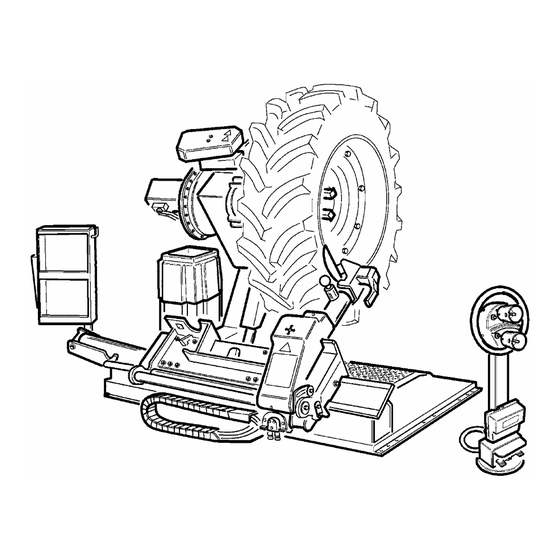
Page 7: Layout Of Functional Parts
LAYOUT OF FUNCTIONAL PARTS 1 - Lifting bracket 2 - Self-centering chuck holding arm 3 - Self-centering chuck 4 - Sliding ramp WARNING! 5 - Switch During all operations, keep hands and other parts of the body 8 - Handler as far as possible from moving parts of the machine. -
Page 8: Identifying Warning Signals
IDENTIFYING WARNING SIGNALS WARNING: Unreadable and missing warning labels must be replaced immediately. Do not use the tyre changer if one or more labels are missing. Do not add any object that could prevent the operator from seeing the labels.Use ref. code #2019225 to order labels set, if needed. -
Page 9: Identification Of Control
CONTROLS DESCRIPTION The mobile control unit (C) enables the operator to work at any position around the machine. On this mobile control unit controls are located: -The lever (8, fig. C) : which in position position [a] lifts the chuck arm, and in position [b] lowers it; in position [c] moves the tool holder arm and the sliding ramp towards the self-centering chuck, and in position [d] moves them away. - Page 10 DANGER! When the spindle carrier arm is lowered, there is always a potential for crushing anything in its movement range. Always work from the position given in the instructions keep well out of the working range of the vari- ous moving arms. Move the joystick towards the lift (c): the tool carriage and the mobile platform (13, Fig.
-
Page 11: Operation
OPERATION RIM CLAMPING 13.1 WARNING! In rim clamping, make sure that jaws are properly positioned on the rim, so as to prevent the tire from falling over 1) Take the mobile control unit to work position B. 2) Pull the tool-holder arm (14, fig. D) into the upright position. 3) Operating from the mobile control centre, move the sliding table (13, fig. -
Page 12: Light-Alloy Rim Locking 13.2 Tubeless And Supersingle Wheels
DANGER! Do not very the work area with a wheel clamped on the tire changer and lifted up from the floor. TUBELESS AND SUPERSINGLE TIRES 13.2 BEAD LOOSENING 1) Clamp the tire assembly on the self-centering chuck, as previously described, and ensure that the tire is deflated. 2) Take the mobile control unit to work position C. -
Page 13: Demounting
Remember that the stronger the tire’s adherence to the rim, the slower must be the disk’s penetration. 7) Move the tool carrier arm (14, Fig. F) back from the edge of the rim. Release the hook, raise the arm to its non-working position, shift it and rehook it in its second work position (Fig. - Page 14 -Place the tool carrier arm in the working position, then the bead disk to push against the inside face of the tire (see fig. H). It’s is best to do this with the wheel turning. Take the mobile control unit to work position B. -Always keep the rotating counterclockwise, while pushing with the bead disk.
- Page 15 Take the mobile control unit to work position C. 6) Position the bead loosener disk against the second bead of the tire and turn the spindle until the g-clamp is at the low point (at 6 o’clock). 7) Move the disk away from the tire assembly. 8) Remove the g-clamp and riposition it at 6 o’clock outside the second bead (See Fig.
-
Page 16: Mounting
MOUNTING WITH THE HOOKED TOOL 1) Follow the steps described in points 1,2,3,4,5 for mounting with the disk. 2) Move the tool carrier arm to its non-working position. Move it to the inside face of the tire and rehook it at this position. 3) Check to make sure the hook tool is positioned facing the tire bead. -
Page 17: Mounting
1) Tip the tool carrier arm (14, Fig. D) to its non-working position. Move it to the outside face of the tire and rehook it in this position. 2) Rotate the tire assembly and at the same time move the hook tool (18, Fig. D) forward inserting it between rim and bead until it is anchored to the tool. - Page 18 Take the mobile control unit to work position B. 4) Put the tire on the ramp and lower the spindle (make sure the g-clamp is at the high point) to hook the first bead on the g-clamp. 5) Lift the rim with the tire hooked to it and turn it counterclockwise about 6-8 inches (15-20 cm). The tyre will be positioned inclined across the rim.
- Page 19 16) Turn the spindle until the valve is at the bottom (6 o’clock). 17) Inflate the inner tube a little (until it has no folds) so as not to pinch it while mounting the second bead. 18) Attach an extension to the valve and then remove the locking ring. The purpose of this operation is to allow the valve to be loose so that it is not ripped out during second bead mounting.
-
Page 20: Wheels With Split Ring
30) Move the ramp to release the tire from the spindle. 31) Remove the tire. TIRES WITH SPLIT RING 13.4 BEAD LOOSENING AND DEMOUNTING TIRE ASSEMBLIES WITH 3-PIECE RINGS 1) Clamp the tire assembly on the spindle as described previously and check to make sure it has been deflated. 2) Take the mobile control unit to work position B. - Page 21 2) Lower the tool carrier arm (14, Fig. D) to its work position until its hook has engaged into position on the carriage. 3) Use the joystick to position the wheel so that the bead loosener disk touches up against outside edge of the centre well rim. 4) Turn the spindle and at the same time move the bead loosener disk forward until the split-ring is detached.
-
Page 22: Mounting
MOUNTING TIRE ASSEMBLY WITH 3-PIECE SPLIT-RINGS 1) Move the tool carrier arm to its non-working position. If the rim has been removed from the spindle, put it back on the spindle as de- scribed in the section on “RIM CLAMPING”. If the tire is tubed, position the rim with the valve slot at the bottom (6 o’clock). -
Page 23: Ordinary Maintenance
7) Move the tool carrier arm to the outside in its work position with the bead loosener disk facing the tire. If the split-ring is not inserted sufficiently on the rim, move the spindle until the split-ring is by the disk. Bring the disk forward (with the spindle turning) until you “observe”... -
Page 24: Trouble Shooting
TROUBLE SHOOTING After having switched on the main power switch on After having switched on the main power switch the electric pack, the general warning light does not on the electric pack the general warning light also TROUBLE SHOOTING light on and no control can function. switches on but the motor on the hydraulic power pack does not function. -
Page 25: 19- Data On Serial Plate
DATA ON SERIAL PLATE The manufacturer’s Serial plate is fixed on the back of the machine. If gives the following information: 1- Manufacturer information 2- Model 3- Serial number Nr. [3] Type: 4- Phases 5- Voltage requirements Kw: [10] Volt: Amp: 6- Frequency 7- Rated draw... -
Page 26: Electric Diagram
HENNESSY Industries, INC 1601 J.P . Hennessy Drive, LaVergne, TN 37086 USA Toll Free 800-688-6496 www.ammcoats.com...
Need help?
Do you have a question about the CHD-9551 and is the answer not in the manual?
Questions and answers