
Subscribe to Our Youtube Channel
Related Manuals for Azbil HGC303

Summary of Contents for Azbil HGC303
- Page 1 CM2-HGC100-2001 Heat Value Gas Chromatograph Model HGC303 User's Manual HGC000001000P...
- Page 2 In no event shall Azbil Corporation be liable to anyone for any indirect, special or consequential damages. This information and specifications in this document are subject to change without notice.
- Page 3 Safety Safety symbols Be sure to correctly operate the model HGC303 while strictly observing the safety precautions provided in this manual-especially the Warnings and Cautions indicated by the symbols as shown below. The descriptions of the Warning and Caution signs used in this manual are as follows.
- Page 4 WARNING NEVER open the terminal box cover while the model HGC303 is energized in a hazardous location. CAUTION Use the model HGC303 only in an ambient temperature of -10 to 50°C (14 to 122°F)
- Page 5 (1) Installation for ISSeP/ATEX Flameproof Apparatus 1. General 1.1 The apparatus protected by the flameproof enclosure in accordance with EN 60079-1 can be installed in such hazardous areas, for which the apparatus has been certified, as an explosive atmosphere containing flammable substances in the form of gas, vapour, mist or dust may be present.
- Page 6 2. Cable systems 2.1 Thermoplastic sheathed cables, thermosetting sheathed cables, or elastomeric sheathed cables can be selected for fixed wiring in the hazardous areas. 2.2 Flameproof cable entry devices (cable glands) certified to comply with EN 60079-1 and appropriate to the type of cable employed, must be used for the connection of cables to the apparatus.
- Page 7 (2) Installation for FM Explosionproof / Flameproof Apparatus (in accordance with NEC) CAUTION • Install the apparatus only in hazardous (classified) locations for which the apparatus has been approved. • Seal each conduit entering the apparatus enclosure within 18 in.(457 mm) from the enclosure. •...
- Page 8 1. Class I, Division 1 locations 1.1 Wiring methods • Threaded rigid metal conduit, threaded steel intermediate metal conduit, or Type MI cable with termination fittings approved for the location, can be employed • Threaded joints must be made up with at least five threads fully engaged. •...
- Page 9 4. Class II, Division 2 locations 4.1 Wiring methods • Rigid metal conduit, intermediate metal conduit, electrical metallic tubing, dust-tight wireways, or Type MC or MI cable with approved termination fittings, or Type PLTC in cable trays, or Type ITC in cable trays, or Type MC or TC cable installed in ladder, ventilated trough, or ventilated channel cable trays in a single layer, with a space not less than the larger cable diameter between the two adjacent cables, can be...
- Page 10 (3) NEPSI Flameproof and Dust Certifications Heat Value Gas Chromatograph model HGC303, manufactured by Azbil Corporation, has been approved by National Supervision and Inspection Center for Explosion Protection and Safety of Instrumentation (NEPSI) in accordance with the following standards: GB3836.1-2010...
- Page 11 EMC caution 1. Electromagnetic environment The model HGC303 is intended to be used in an industrial electromagnetic environment. 2. Electromagnetic immunity conditions Specification: During test, SCV deviation is less than or equal to 1MJ/m...
-
Page 13: Table Of Contents
2-5-3. Model HGC303 installation example ........ - Page 14 4-2. Checking and changing the filters in model HGC303 ....... .
-
Page 15: Chapter 1. Introduction
6976 and GPA2172. HGC000 HGC Data Manager (Model HDM303) Model HDM303 is Modbus interface unit for model HGC303. Model HDM303 covers all the function of model HMU303. Model HDM303 also has a powerful functions. The functions are local display, data storage function, multi Modbus serial port, multi stream switching, and analog output. - Page 16 HGM software is provided as a standard accessory with the model HGC303. The model HGC303 Monitor allows the user to configure and calibrate the model HGC303 as well as allowing one to monitor a heat value-trend graph. Moreover, HGM also has a report function for concise management.
-
Page 17: General
1-2. General The model HGC303 is a gas chromatograph designed to analyze natural gas and is able to transmit a process variable via a Fieldbus signal. One can easily adjust configuration data and monitor values such as the heat value by using the HGM. -
Page 18: Model Hgc303 Measuring System
1-3. Model HGC303 measuring system Fig. 1-1 Model HGC303 measuring system diagram CAUTION A block valve is a kind of air actuator valve. It is used mainly for the protection of the TCD and columns. It works as sample shut-off valve when the pressure of the carrier gas or air supply is lower than approximately 294 kPa. -
Page 19: Model No
1-4. Model No. Heat Value Gas Chromatograph HGC303-I II Conduit entry 1/2 NPT female Gas connection 1/4 NPT female Calculation method Explosion-protection ISSeP/ATEX flameproof NEPSI flameproof TestSafe flameproof JIS flameproof * + Ordinary type + FM flameproof CSA flameproof Note *: Special model. -
Page 20: Model Hgc303 Structure
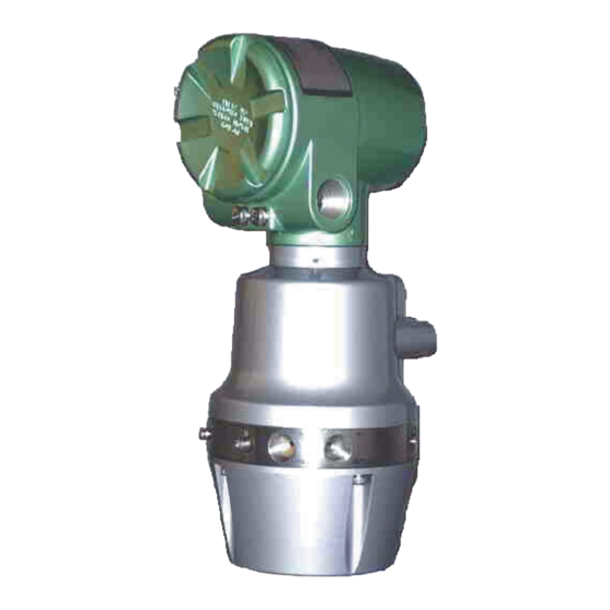
Manifold Oven cover HGC000004000D Fig. 1-2 Main parts of Model HGC303 1 Terminal housing ..Terminal box for wiring. 2 Analyzer unit housing ..Proportional valve, solenoid valve, TCD sensor are located here. 3 Manifold ......Connection parts for gas inlet and outlet line... -
Page 21: Fieldbus Communication System
1-6. Fieldbus communication system The model HGC303 uses F fieldbus technology to transfer information OUNDATION between other devices. The F fieldbus is an open, 2-wire, multi-drop, two-way digital OU N DAT ION communication system which interconnects field equipment such as sensors, actuators and controllers. -
Page 23: Chapter 2. Installation
2-1. Unpacking and storing Unpacking the model HGC303 Your model HGC303 is a precision instrument and should be handled with care to prevent any damage to it or breaking it. After unpacking the model HGC303, verify that the following items are included... - Page 24 - indoor at storage temperature (-40 to 70 °C); humidity (up to 95%RH) - in a place safe from vibration or shock. - in the same packing as it was shipped in. Model HGC303 that has been used should be stored by following procedures below. Step Action Make sure no process gas remain in the model HGC303.
-
Page 25: Installing The Model Hfa100
2-2. Installing the model HFA100 To collect data from HGC, HGM needs the HFA100 (Heat value gas chromatograph fieldbus adapter) as a data converter. First, for hardware installation, see the user’s manual for HFA100. Note: This manual is for the use of HFA100 version 3.0 or later. For combinations of HFA100 versions and corresponding PC software versions, see “Software Compatibility”... -
Page 26: Settings For Windows 10
2-3-2. Settings for Windows 10 When using Windows 10 and running the HGM online, make sure to configure the Windows Update setting so that the Internet is not connected. Stopping services (1) Left-click the [Start] icon and then click the [Services] menu from the [Windows Administrative Tools]menu. - Page 27 (2) Click in the [Services] screen, and then right-click [Windows Update]. (3) On the [Services] screen, right-click [Windows Update] and then click [Properties] in the menu that is displayed.
- Page 28 (4) On the [Windows Update Properties] screen, click [Startup type] and then switch it to [Disabled]. If [Service Status] is [Run], switch it to [Stopped]. (5) On the [Windows Update Properties] screen, with the [Startup type] selected as [Disabled], click the [Apply] button and then the [OK] button.
- Page 29 (6) Click on the search section at the bottom left of the window. (7) Click in the Search screen and enter “gpedit.msc. ” (8) Right-click the displayed program and click “Run with Administrator Privileges. ” (9) The [Local Group Policy Editor screen] opens.
- Page 30 (10) In the [Local Group Policy Editor] screen, click [Computer Configuration] > [Administrative Templates] in the menu tree on the left. (11) Click [Windows Components] in the [Local Group Policy Editor] screen.
- Page 31 (12) Double-click [Windows Update] in the [Local Group Policy Editor] screen. (13) Double-click [Configure Automatic Update] in the [Local Group Policy Editor] screen. (14) Click the [Disabled] button in the [Configure Automatic Update] screen.
- Page 32 (15) Click the [OK] button in the [Configure Automatic Update] screen. (16) In the Settings screen, click the [Update & security] icon. 2-10...
- Page 33 (17) Open the [Windows Update] item list. (18) In the [Windows Update] items list, click [Advanced options]. 2-11...
- Page 34 (19) Below the [Choose how updates are installed] section, if “Some settings are managed by your organization” is displayed and grayed out, the settings for Windows 10 are complete. 2-12...
-
Page 35: Hgm Software Installation
2-3-3. HGM software installation Installing the HGM. Note: We recommend always using the latest version of the HGM software. It is supplied in HGC CD-ROM. (1) Make sure Windows has been installed. (2) Start PC. Be sure to Log On your PC with Administrator Account. (3) Insert the CD-ROM that is supplied with HGC into the CD-ROM drive. - Page 36 (7) HGM installer will appear, click [OK] button. Fig. 2-2 Setup message (8) The following screen will appear, click PC figure button. Fig. 2-3 HGM installation location 2-14...
- Page 37 (9) The following screen will appear, click [Continue] button. Fig. 2-4 Group name If a version conflict message appears, select [Yes]. (10) Installation is complete once the message below appears on your screen. Click [OK] button. Fig. 2-5 Complete installation 2-15...
-
Page 38: Net Framework 4.0 Installation
2-3-4. .NET framework 4.0 installation Do the installation if the OS is Windows 7 Microsoft .NET framework 4.0 or later is required to run HGM. If Microsoft .NET framework 4.0 or later is not installed on the PC, install it using the following proce- dure. (1) Make sure Windows has been installed. - Page 39 (7) Setup program will start. Fig. 2-7 .NET framework 4.0 installation progress Check the license acceptance check box and click the [Install] button. (8) Installation will start. It may take a few minutes until completion. Fig. 2-8 .NET framework 4.0 installation progress 2-17...
-
Page 40: Microsoft Visual C++ Runtime Installation
(9) Installation is complete once the message below appears on your screen. Click [Finish] button. Fig. 2-9 Complete installation 2-3-5. Microsoft Visual C++ runtime installation The runtime component for Microsoft Visual C++ 2010 is required for HGM execution. If it is not installed on the PC, install it using the following procedure. - Page 41 Fig. 2-10 UAC dialog box (7) Setup program will start. Fig. 2-11 VC++2010 runtime license agreement Check the license acceptance check box and click the [Install] button. 2-19...
- Page 42 (8) Installation will start. Please wait a moment. Fig. 2-12 VC++2010 runtime installation progress (9) Installation is complete once the message below appears on your screen. Click [Finish] button. Fig. 2-13 Complete installation 2-20...
-
Page 43: Setting The Folder Access Rights
2-3-6. Setting the folder access rights When executing HGM on a Windows 7 or later PC, full access rights for the following program folders are required. 32bit type operation system: C:\Program Files (x86)\HGM 64bit type operation system: C:\Program Files\HGM Note: Executing the program without this setting will cause a virtual folder problem caused by Windows User Account Control (UAC). - Page 44 (3) HGM Properties, select [Security] tab and click [Edit] button. Fig. 2-15 HGM folder properties 2-22...
- Page 45 (4) Permissions for HGM, select [Users] in Group or user names. Fig. 2-16 Permissions for HGM folder 2-23...
- Page 46 (5) Permissions for HGM, check Allow Full control in Permissions for Users, then click [Apply] button and click [OK] button. Fig. 2-17 Permissions for HGM folder 2-24...
-
Page 47: Fieldbus Installation
HGM folder. 2-4. Fieldbus installation 2-4-1. Fieldbus requirements Fieldbus components and characteristics Cable Various types cables are usable for fieldbus. Type A is the preferred fieldbus cable. Azbil Corporation recommends type A as the fieldbus cable to use. 2-25... - Page 48 The table below describes the type of cable and its maximum length, which is specified in the IEC 1158-2/ISA S50.02 Physical Layer Standard. Table 2-1. Fieldbus cable description Type Cable description Size Maximum length Shielded, twisted pair #18 AWG (0.8 mm 1900m (6232 ft.) Structure: twisted pair cable with overall shield Detailed specifications of the Type A cable at 25 °C are as follows;...
- Page 49 The terminator impedance value shall be 100 ohm +/- 2% over a frequency range of 7.8 kHz to 39 kHz. The model HGC303 and model HDM303 have a terminator at the fieldbus connection port therefore an additional terminator is not required.
-
Page 50: Fieldbus Wiring
2-4-2. Fieldbus wiring Signal wire A Fieldbus signal is transmitted via 2-wire isolated signal lines. Please keep in mind that the Fieldbus signal has polarity, positive (+) and negative (-). All of the (+) terminals must be connected to each other and similarly, all of the (-) terminals must be connected each other. -
Page 51: Model Hgc303 Installation
- A sheltered location conforming to class C as defined by IEC654-1. This is so to protect the model HGC303 from direct sunlight, wind, and rain. Select a site that allows for the installation of a housing structure or protective panels. -
Page 52: Model Hgc303 Dimensions
2-5-2. Model HGC303 dimensions The dimensions of the model HGC303 are given below. [Unit: mm (inch)] 115 (4.5) 77 (3.0) 100 (3.9) Fig. 2-21 Model HGC303 dimension A workspace should be selected taking into consideration facilitation of wiring, piping, and maintenance. -
Page 53: Model Hgc303 Installation Example
2-5-3. Model HGC303 installation example Install the model HGC303 as shown in following diagrams. The weight of the model HGC303 with mounting bracket is 5 kg / 11 lbs. 2in. pipe Hexagon head bolt Mounting bracket HGC000008000D Fig. 2-22 Example of model HGC303 installation with mounting bracket Mounting position: Mount the model HGC303 horizontally. -
Page 54: Model Hgc303 Piping
Outlet for mixture of measured gas and carrier gas Measured gas outlet TCD-VENT after analysis. Note *: Remove the vent plug then connect the fitting and pipe when IP65 is required or when HGC model No. is ‘HGC303-1S’ . 2-32... - Page 55 WARNING Purge the carrier gas line before performing any piping, and then verify that there is no dust remaining in the piping. Release the gas from the vent line to the air through the header. There is a possibility that back-pressure from vent line has a lot of influence. Prepare the carrier gas and valve operating gas as specified in the table below.
-
Page 56: Model Hgc303 Wiring
No connection FB terminal (-) FB terminal (+) No connection Terminator (-) Terminator (+) Internal GND External GND Note: Azbil Corporation recommends cable of conductor cross-sectional area 2 (mm ) or equivalent for power supply connection and GND connection. 2-34... - Page 57 WARNING Only a 24V DC supply may be used to operate the model HGC303. CAUTION Confirm that the supply voltage is within 24VDC+/-15% (20.4~27.4V) at the HGC terminal. CAUTION HGC requires the current of 4A minimum on 24VDC as the power supply.
- Page 58 2-36...
-
Page 59: Chapter 3. Operation
Process gas 50 ± 20 ml/min. 3-1-2. Piping leak check Before starting up the model HGC303, conduct a leak test to verify there is no leakage of gas from the piping connection. A leak test using soap bubbles will be sufficient. -
Page 60: Power On
Oven temperature SP: 58°C (136.4°F) Analyzing cycle: 300 sec. Note: When the power is supplied to the model HGC303, a model HGC303 status error will appear on HGM monitoring system (oven temperature error message etc. This is because of a self-diagnostic system error, not a model HGC303 system error. -
Page 61: Model Hgc303 Leak Check
3-1-4. Model HGC303 leak check After turning the model HGC303 on, conduct a leak test to verify that there is no leakage of gas from the model HGC303. The following procedures are for a simple leak test for the carrier gas line. Carry out the leak test for the valve operating gas line in the same way. -
Page 62: Stopping The Model Hgc303
Shut off the valve operating gas line. Refer to “ Storing the model HGC303” on page 2-2 when removing the model HGC303 from the field. CAUTION Do not leave the model HGC303 in the sampling system without plugs or seals at the connections to vent. -
Page 63: Hgm Operation
Introduction The functions of the HGM are described in this chapter. The HGM is a calibration, configuration and maintenance tool for the model HGC303. Analysis statuses, process variables and a chromatogram are displayed on its screen, and information is stored in a database to facilitate routine management and tuning. -
Page 64: Hgm Connection With Model Hfa100 And Hdm303
HGM connection is possible at any location along the FB line. Connect the HGM as shown in the picture below. Fig. 3-2 Model HGC303-HGM connection example (combination of model HGC303, model HDM303 and model HFA100) Refer to the model HDM303 user’s manual regarding the details of each part of the model... -
Page 65: Starting Up The Hgm With Model Hfa100
3-3-2. Starting up the HGM with model HFA100 The procedure to start the HGM up are given below. (1) Make sure that both the model HGC303 and the model HDM303 are running normally. (2) Prepare a personal computer, which has the HGM installed. - Page 66 (8) Port setting combo box will appear, click [ ], and select COM port for use, and click [OK] button. Fig. 3-3 HFA Port setting These settings will be stored in the settings file in the program folder.
- Page 67 (9) Run the driver program [hfadrv2.exe] All program> HGM> hfadrv2 (10) Driver program will start, and please wait for periodical running begin. Fig. 3-4 hfadrv2 comand window Note: When the driver program doesn’t operate properly, please Refer to troubleshooting “5-1. Connection with PC.
- Page 68 (11) Run the HGM program [hgmXXX.exe]. All program> HGM> HGM VersionX.XX HGM Program will start. Fig. 3-5 start HGM 3-10...
- Page 69 HGM operation flow chart Here is a flow chart showing how to get the HGM online and it also gives an overview of the HGM’s functions. [hfadrv2.exe] [hgmXXX.exe] [hgmXXX.exe] [hfadrv2.exe] Below is a flowchart showing HGM functions that are available offline. [hgmXXX.exe] [hgmXXX.exe] 3-11...
-
Page 70: Hgm Main Menu
Select Online/Offline mode, Data saving interval. Monitoring heat value trend graph and chromatogram. You can User‘s Mode also perform calibrations using this mode. The model HGC303 can be configured from here can be done Configuration mode here. Quit Exit from the HGM application. -
Page 71: Set Up Hgm
3-3-4. Set up HGM Before the HGM can communicate with the model HGC303, an initial setup must be performed as follows. a. Initial screen b. After clicking the [Change password] button. c. Normalization method setting Fig. 3-7 Set up HGM display... - Page 72 The HGM displays the value of after normalization, by following Normalization the method which has set. See section “3-3-8. Configuration method mode” to set HGM to HGC. Follow the procedures given below in order for the HGM to communicate with the model HGC303. 3-14...
- Page 73 Select [HGC] in Analyzer Status If [HGC] cannot be selected from the pull-down menu, click the [Refresh] button. The HGM searches for the model HGC303 again along the Fieldbus line. [Data saving interval] Select “data saving interval” from pull-down menu;...
- Page 74 Table 3-8. Analyzer status and available functions Analyzer Status Print Save Load Report Calibration Online Offline NA: not available Note: For details on [GPA mode] selected in Calculation mode, refer to “3-5. GPA mode” on page 3-52. Data save The last 4000 items of data are automatically stored in the RAM of your PC at each data saving interval.
- Page 75 Editing data If you want to edit saved data, open a saved file using to following procedure. You can edit data using software such as Microsoft Excel 1 Start Microsoft Excel 2 Select [Open] 3 Select the directory where the saved file is stored. (Default directory C:\program files\hgm\data) 4 Select [All files] in “Files of type”.
- Page 76 Automatic file saving The HGM can be set to automatically save data files. This is done by activating the setting from the [setup HGM] panel. Default directory; C:\program files\hgm\data. Files with the extensions;.hv1,.cv1, and.sv1 and.cg1(chromatogram) are saved. All.cg1 files are saved as named YYYYMMDDHHMMas.cg1. YYYY = year, MM = month, DD = date, HH = hour, MM = minute, as = auto saving, .cg1 = chromatogram extension file.
-
Page 77: User's Mode Menu And Commands
3-3-5. User’s mode menu and commands Click on [User’s Mode] and you will see the following display. The display size is fixed (full screen). Fig. 3-9 User’s mode display This screen is divided into three graphs. On the right hand side is the measurement data. Table 3-10. -
Page 78: Main Displays Of Hgm
XX: 01-299 Return to [latest] to monitor the latest chromatogram. Auto reload function starts again. Model HGC303 holds outputs to the host control system during field maintenance. [Field work] Click the [Field work] button then [ON], to set the holding time to [24hrs]. [Field work] button blinks while performing fieldwork. - Page 79 Heat value and total raw concentration This graph shows the heat value and the total raw concentration. The left vertical axis represents the heat value and the right vertical axis represents the total raw concentration. The horizontal axis represents the time range. HGM000016000S Fig.
- Page 80 Chromatogram Chromatogram is updated every 5 minutes. HGM000017000S Fig. 3-11 Trend chromatogram (online) Table 3-13. Chromatogram description Display Description Upper Range Value for vertical axis Click the [URV] button to change the URV value Default value is 1 Load (Offline) Recall saved data.
- Page 81 Zoom function (2 × 2) Click on a peak of interest to get a detailed view (display only). Fig. 3-12 Zoom box 3-23...
- Page 82 Trend graph of carrier gas pressure and oven temperature control HGM000019000S Fig. 3-13 Trend graph of carrier pressure and oven temp. control This data is displayed according to the set data saving interval (Refer to “3-3-4. Set up HGM” on page 3-13). Default interval: 5 sec.
-
Page 83: Report
3-3-7. Report To create a report, click the [report] icon in the right panel of User’s mode. The following entry form for process gas data will appear. HGM000020000S Fig. 3-14 User report entry form Enter the necessary items and click the [Preview] button. It is not necessary to fill out all of the boxes. - Page 84 HGC 303 Analysis Report Source Report Date - Time Oct-18-2007 13:41:50 Station Analysis Date - Time Jul-24-2007 11:38:00 Station Name Process Pressure Field Process Temp. File Name C:\ Program Files\ HGM_HFA\ DATA\ 07072400.CG1 Gas Analysis by HGC 303 Name Raw mol % Normalized mol % 0.051 0.051...
- Page 85 Display of user input data and saved file name Gas Analysis by model PV1 -11 outputs data from model HGC303 HGC303 HGC Outputs Display of model HGC303 configuration data (PV12 -20) Configuration data Heatvalue Calculation by All heat value data is calculated by the HGM and is displayed.
-
Page 86: Configuration Mode
3-3-8. Configuration mode Various configurations of the model HGC303 and the HGM can be made in this mode. Click on [Configuration mode] in the main menu. The following screen will appear after entering the password. Fig. 3-16 Configuration mode display Note: Some items of PV12-15, 19 and 20 may not be available. - Page 87 HGC (version 3.0 or later) and HDM (version 2.30 or later) combination. Download to HGC All configured data are downloaded to the model HGC303 by clicking this button. Return Menu Exit from configuration mode.
- Page 88 (1) PV1 - 11 configuration (1-1) Low cut off: Threshold of a peak or a noise If the detected value < low cut off value, the output will be transmitted as 0 mol%. (1-2) % DEV RF limit: See “3-4-2. Calibration procedure” on page 3-42 for details Each RF %dev limit can be set independently.
- Page 89 (2) PV12 -20 configuration PV12 to 15, 19 and 20 can be configured to set which outputs are transmitted to the host control system. 3-31...
- Page 90 Possible configurations of each PV are as follows. Table 3-17. Possible configurations of PV12-20 PV12 Choose one from followings as a PV12 output value. ISO SCV(real) (MJ/m ) [ISO default] ISO SCV(ideal) (MJ/m ISO ICV(real) (MJ/m ISO ICV(ideal) (MJ/m Following setting is available for application of HGC (version 3.1 or later), HGM (version 4.70 or later) and HDM (version 2.40 or later) combination.
- Page 91 Table 3-17. Possible configurations of PV12-20 PV14 Choose one from followings as a PV14 output value. ISO Wobbe Index (real) (MJ/m ) [ISO default] ISO Wobbe Index (ideal) (MJ/m Following setting is available for application of HGC (version 3.1 or later), HGM (version 4.70 or later) and HDM (version 2.40 or later) combination.
- Page 92 Table 3-17. Possible configurations of PV12-20 PV19 Choose one from followings as a PV19 output value. ISO ICV (real) (MJ/m ) [ISO default] ISO ICV (ideal) (MJ/m Following setting is available for application of HGC (version 3.1 or later), HGM (version 4.70 or later) and HDM (version 2.40 or later) combination. ISO ICV (real) (kJ/m ISO ICV (ideal) (kJ/m ISO ICV (real) (kWh/m...
- Page 93 (3) PV High/Low Alarm Configuration Click on [PV High/Low Alarm Configuration] in the configuration mode display. The following screen will appear. To change the limit value, type the value directly to the High or Low Limit box: Default value PV1-11 Low 0, High 100 PV12-15, 19 and 20 Low 0, High 10000...
- Page 94 (4) Output setting in Auto Calibration Data update to the HDM during auto or semi-auto calibration can be selected after executing auto or semi-auto calibration. - Hold [default] - Calibration data (New RF) If “Hold” is selected, the HGC does not update the data to the HDM during auto/semi-auto calibration.
- Page 95 (5) Reference conditions Configuration data for heat value calculation can be selected or input manually. (5-1) Combustion temperature / Metering temperature These can be selected in compliance to the ISO6976. • 15/15 °C [Default] • 0/0 °C • 15/0 °C •...
- Page 96 (6) Total of raw concentration Usually, the total of raw concentration is within 95-105 mol% during natural gas analysis. In these values are required to be changed, input a user defined value for both high and low limit. When these values exceed the limitations, the color of the “HGC Status” box turns to red in user’s mode.
- Page 97 (8) Multi-stream function setting When you use HGC without multi-stream function, please select “Not use multi-stream function” (default) and download to HGC to inactivate the multi stream function. When you use HGC with multi-stream function, please select “Use multi-stream function” and download to HGC to activate the multi stream function.
-
Page 98: Hgm Shut Down
3-3-9. HGM shut down Table 3-18. Stopping the HGM Step Action Click on [Return Menu] Click on [Quit] Wait until the hfadrv2 command screen closes. 3-40... -
Page 99: Calibration
3 At a calibration interval decided by the user. (Recommended calibration cycle is every 6 months.) 4 After the model HGC303 has been repaired or its parts have been replaced. 3-4-1. Calibration gas requirement 1 It is imperative that the composition of the calibration gas should resemble the process gas. -
Page 100: Calibration Procedure
3-4-2. Calibration procedure The model HGC303 has two calibration methods. Each calibration procedure is described below. Manual calibration Manual calibration procedure is as follows: Manual calibration Online HGM User’s mode Change the inlet gas from sample gas to calibration gas ... - Page 101 The setting is activated once the [start] button in auto calibration box is pressed. (Fig. 3-17) (It’s not always necessary that the HGM is communicating with the model HGC303 after these settings have been made.) An example of a calibration time chart is shown below.
- Page 102 RF% DEV = × 100 % DEV RF Limit The model HGC303 automatically calculates a “RF% DEV” and decides whether the value is smaller than the “% DEV RF Limit” or not. |RF% DEV| ≤ “%DEV RF Limit” => “OK”...
- Page 103 Table 3-19. Example of calibration action Signal to Calibration OLD RF NEW RF Judgement model HDM303 Auto Auto Auto Manual NG=>OK Auto Auto Manual Auto Bold: Valid response factor Semi Auto calibration The semi auto calibration function will perform auto calibration sequence triggered by pressing [start] button operation.
-
Page 104: Calibration Function
3-4-3. Calibration function Click the [calibration] icon in User’s mode. The calibration setting panel (Refer to “ Indication panel” on page 3-20) will then appear. Fig. 3-17 Calibration setting panel 3-46... - Page 105 Click the [download] button and the present time will be downloaded to the model HGC303. If the model HGC303 is turned off, the time setting will be reset to [0:00]. Please set the time again before performing auto calibration. Component Data Table Refer to “3-4-4.
-
Page 106: Description Of Component Data Table
Table 3-20. Calibration factor setting Display Description Calibration Method 1 point [default] and 3 points calibration can be selected.1 point is calibration using data of one analysis.3 points is calibration using data of last three analysis average.This function is available for application of HGC (version 3.1 or later) and HGM (version 4.70 or later) combination. -
Page 107: Report
New RF will be used as the response factor. If an NG message appears, no components will be calibrated and the Old RF will be used as the response factor and the model HGC303 will transmit an “RF error” to the host control system via the model HDM303. -
Page 108: Calibration Methods
3-4-6. Calibration methods The model HGC303 has three-calibration methods, manual, automatic and semi automatic. Manual calibration Table 3-22. Manual calibration procedure Step Action Select [Manual calibration]. Recall the saved calibration data or input concentration of each component manually. Perform calibration by following the flow chart below. - Page 109 Auto calibration Table 3-23. Operating auto calibration procedure Step Action Set the model HGC303 Time Adjusting to the present time. Select [Auto calibration]. Choose a [Time], [Interval], [Hold time] (Refer to “Table 3-20. Calibration factor setting” on page 3-47.) Recall the saved calibration data or input concentration of each component manually, then check the small box.
-
Page 110: Gpa Mode
3-5. GPA mode Perform the following procedures when the HGM is used in GPA mode. 3-5-1. Setting the HGM to GPA (1) Set the HGM online as described in “3-3-2 : Starting up the HGM with model HFA100” on page 3-8. (2) Select [GPA] from calculation mode in the Setup HGM screen. -
Page 111: Data Save
3-5-2. Data save The mechanism is same as for ISO mode. (Refer to “3-3-4. Set up HGM” on page 3-13) The data is saved as text files (.hv2 or.cv1 or.sv2) in C:\program files\hgm\data (Default). In the case of 64bit type operation system, data are saved in c:\Program files (x86)\hgm\data Note: The file (.sv2) includes date/time, oven temperature (unit: °F) and carrier gas pressure (unit: psi). -
Page 112: File Auto Saving
The contents of each line of.hv2 are described below. Table 3-25. The contents of each line of.hv2 Displayed name Full name Date / Time YYYY/MM/DD HH:MM:SS Total (raw) Total raw concentration rGHVdry real Gross Heating Value dry rGHVsat real Gross Heating Value sat rNHVdry real Net Heating Value dry rNHVsat... -
Page 113: Configuration Mode
3-5-5. Configuration mode Numerous configurations of the model HGC303 and the HGM can be done in this mode. Click on [Configuration mode] from the main menu. The following screen appears after entering the password. Fig. 3-23 Configuration mode display (GPA) Table 3-26. - Page 114 This setting is only available for application of HGC (version 3.0 or later) and HDM (version 2.30 or later) combination. Download to HGC All configured data are downloaded to the model HGC303 by clicking this button. When the message appears, download operation has been successfully completed.
- Page 115 (2) PV12 - 20 configuration PV12 to 15, 19 and 20 can be configured to set which outputs are to be transmitted to the host control system. Fig. 3-24 Output configuration panel (GPA) 3-57...
- Page 116 Possible configurations for each PV are as follows: Table 3-27. Possible configurations of PV12-20 (GPA) PV12 Choose one from followings as a PV12 output value. GPA Real Gross HV(dry) (BTU/CF) [GPA default] GPA Real Gross HV(sat) (BTU/CF) GPA Ideal Gross HV(dry) (BTU/CF) GPA Ideal Gross HV(sat) (BTU/CF) GPA Gross HV(dry) (BTU/lbm) Following setting is available for application of HGC (version 3.1 or later), HGM...
- Page 117 Table 3-27. Possible configurations of PV12-20 (GPA) PV14 Choose one from followings as a PV14 output value. GPA Real Wobbe Index (dry) [GPA default] GPA Real Wobbe Index (sat) GPA Ideal Wobbe Index (dry) GPA Ideal Wobbe Index (sat) Following setting is available for application of HGC (version 3.1 or later), HGM (version 4.70 or later) and HDM (version 2.40 or later) combination.
- Page 118 Table 3-27. Possible configurations of PV12-20 (GPA) PV19 Choose one from followings as a PV19 output value. GPA Real Net HV (dry) (BTU/CF) [GPA default] GPA Real Net HV (sat) (BTU/CF) GPA Ideal Net HV (dry) (BTU/CF) GPA Ideal Net HV (sat) (BTU/CF) GPA Net HV (dry) (BTU/CF) Following setting is available for application of HGC (version 3.1 or later), HGM (version 4.70 or later) and HDM (version 2.40 or later) combination.
- Page 119 (3) PV High/Low Alarm Configuration Note: These configuration methods are same as those for ISO mode. Refer to “ (3) PV High/ Low Alarm Configuration” on page 3-35. (4) Output setting in Auto Calibration Note: These configuration methods are same as those for ISO mode. Refer to “ (4) Output setting in Auto Calibration”...
- Page 120 (5-2) Base pressure (psi) • 14.50 • 14.696 [Default] • 14.730 • 15.025 • Other value (6) Total of raw concentration Note: These configuration methods are same as those for ISO mode. Refer to “ (6) Total of raw concentration” on page 3-38. (7) Normalization method configuration Note: These configuration methods are same as those for ISO mode.
-
Page 121: User's Mode (Gpa)
3-5-6. User’s mode (GPA) Click on [User’s mode] in the main menu and a display as shown below will appear. The size of the display is fixed (full screen). Fig. 3-25 User’s mode display (GPA) This screen is divided into three graphs with measurement data on the right. Table 3-28. - Page 122 The differences between ISO and GPA mode in User’s mode are given below. Table 3-29. The difference between ISO and GPA mode in user’s mode Item Unit: BTU/CF or Top (Blue) Left vertical axis Unit: MJ/m BTU/lbm Center (white) Chromatogram ISO and GPA use the same display.
-
Page 123: Main Display Panels Of Hgm (Gpa)
Return to [latest] to monitor the latest chromatogram. Auto reload function starts again. [Field work] The model HGC303 holds outputs to the host control system during field maintenance. Click the [Field work] button then [ON], to set the holding time to [24hrs]. [Field work] button blinks while performing fieldwork. - Page 124 Note: Description of calculated value (GPA) Select one of the four items to view the calculated values BTU (dry), BTU (sat), Density, GPM) All calculated values for that item are then displayed. The contents of the calculated values are given below. BTU (dry) BTU (sat) ...
- Page 125 Heat value and total raw concentration Fig. 3-26 BTU trend graph and the total of raw concentration Table 3-31. Trend graph of BTU and Total raw concentration description Display Description URV(BTU) Upper Range Value for BTU, default value: 1150BTU/CF Click the [URV] button to change the URV value Load (Offline) Saved data is recalled.
- Page 126 Chromatogram Fig. 3-27 Trend Chromatogram (online) Table 3-32. Chromatogram description Display Description Upper Range Value for vertical axis Click the [URV] button to change the URV value Default value is 1 Load (Offline) Saved data is recalled. File name extension:.cg1 Save (Online) The latest data is saved.
- Page 127 Trend graph of carrier gas pressure and oven temperature control Fig. 3-28 Trend graph of carrier pressure and oven temp. control Table 3-33. Trend graph of Carrier gas pressure and Oven temperature control Display Description URV (Oven Temp.) Upper Range Value for Oven temperature Click the [URV] button to change the URV value.
- Page 128 3-5-8. Report (GPA) Fig. 3-29 Report entry form (GPA) 3-70...
-
Page 129: Report (Gpa)
HGC 303 Analysis Report Source Report Date - Time Oct-19-2007 15:11:24 Station Analysis Date - Time Jul-18-2007 14:11:00 Station Name Process Pressure Field Process Temp. O(pounds/MMCF) File Name C:\ Program Files\ HGM_HFA\ DATA\ 07071800.CG1 Component M ole Weight LiqVol Gallons/ Gross Relative Name... - Page 130 3-72...
-
Page 131: Chapter 4. Maintenance
At the same time, the model HGC303 inlet line filter should also be replaced. It is recommended to change the filter every 6 months. (See the spare parts list at the back of this manual) 4-3. -
Page 133: Chapter 5. Troubleshooting
HFA100. error Check the FB cable connection with connection HDM303. error Confirm HDM303 powered on. hfadrv2 couldn’t find “HGC303” Check the FB cable connection with Connection HGC303. error Confirm that power is supplied to HGC303. HGM software terminates, or... -
Page 134: Hgc Status On Hgm
HGC303 is running. Click on the error box on the HGM screen to get more detailed information regarding the error. Table 5-1 shows the self-diagnostic functions of the model HGC303. Table 5-1. Model HGC303 self-diagnostics Error message... - Page 135 Table 5-1. Model HGC303 self-diagnostics Error message Error description Action Retention time Ethane (C2) Retention Check the HGC analysis used Standard Gas lock error Time is out of range which contains Ethane. C2 Rt < SP-2sec. or SP+2sec. < C2 Rt...
-
Page 137: Appendix
GPA calculation Description of normalization method The model HGC303 has two kinds of normalization methods. One is the Standard normalization method, and the other is the Methane normalization method. Normalization method is used to derive each component’s normalized concentration from un-normalized components’... - Page 138 * GHV: Gross Heating Value (British Thermal Unit / Cubic Foot) Decide which normalization method should be selected, and configure it to the model HGC303 at the configuration mode. In addition, don’t forget to setup it at the [Setup HGM] screen for HGM.
- Page 139 Formulas This section shows formulas for heat value calculations. 1) Real dry heating value per unit volume 2) Real saturated (sat) heating value per unit volume 3) Dry heating value per unit mass 4) Compressibility factor (dry) 5) Compressibility factor (sat) 6) Real Relative density, gas (dry) 7) Relative density, liquid 8) Gas density...
- Page 140 1) Real dry heating value per unit volume: HV (dry) [BTU/CF] Real GHV (dry) and Real NHV (dry) are calculated using the following formula. Σ xi × ( i = 1 RealGHV (dry) = Z (dry) Z (dry) where, GHV = ideal gross heating value per unit volume (GHV ) i = ideal gross heating value per unit volume for component i...
- Page 141 5) Compressibility factor Z (sat) Compressibility factor (sat) is calculated using the following formula. Z (sat) = 1 – (1 - xw) × (xi × bi) + xw × bw × PB Σ i = 1 bw = summation factor of water where, 6) Real relative density, gas (dry): G Z (dry air)
- Page 142 10) Wobbe index (dry) [BTU/CF] RealGHV (dry) Real Wobbe Index (dry) = Ideal Wobbe Index (dry) = 11) Wobbe index (sat) [BTU/CF] RealGHV (sat) Real Wobbe Index (sat) = (1 - xw) × GHV Ideal Wobbe Index (sat) = 12) Gallons per thousand cubic feet (GPM) [gal /1000CF] ...
- Page 143 16) Specific Heat K × k Σ i = 1 Where, Ki = specific heat for component i Liq. Sum. Vapor Molar Rel. den. Rel. den. den. Volume K= Cp/ Components (BTU/ (BTU/ (BTU/ (BTU/ Factor press. mass liquid (lbm/ (CF/gal) lbm) lbm)
- Page 144 ISO calculation Description of normalization method Model HGC303 has four kinds of normalization methods for ISO calculation. These are Standard normalization, Methane normalization, Helium (variable) normalization and Helium (constant) normalization. You can select one type of normalization. 1 Standard normalization method This method is same as for GPA calculation.
- Page 145 ISO calculation of Calorific value, density, relative density, Wobbe index and compression factor will be calculated using PV1-PV11(normalized) and Helium (normalized). 4 Helium (constant) normalization method Model HGC303 calculates the normalized concentration using total raw and Helium concentration by following formula. Helium Fixed value is used for Helium.
- Page 146 Formulas(ISO6976:1995) This section shows formulas for heat value calculations of ISO6976:1995. 1) Compression factor 2) Superior calorific value 3) Inferior calorific value 4) Density 5) Relative density 6) Wobbe Index 1) Compression factor Zmix Compression factor Zmix = 1 - [sum (xj × sqrt (1 - Zj)) + xhelium × sqrt(b)helium] ^ 2 where, xj = mole fraction for component j xhelium...
- Page 147 4) Density (kg/m Ideal gas density, Density (ideal) = [sum (xj × Mj) + xhelium × Mhelium] × p2 / (R × (t2 + 273.15)) Real gas density, Density (real) = Density (ideal) / Zmix where, xj = mole fraction for component j xhelium = mol fraction for Helium = molar mass for component j (ISO6976 Table 1) Mhelium = molar mass for Helium (ISO6976 Table 1)
- Page 148 Formulas(ISO6976:2016) This section shows formulas for heat value calculations of ISO6976:2016. 1) Compression factor 2) Calorific value on a molar basis Gross calorific value Net calorific value 3) Calorific value on a volume basis Ideal gas gross calorific value Ideal gas net calorific value Real gas gross calorific value Real gas net calorific value 4) Associated properties...
- Page 149 3) Calorific value on a volume basis Ideal gas gross calorific value HvG0 = HcG0 / V0 where ideal molar volume of the mixture, V0 = R * (t2 + 273.15) / p2 gas constant (Table A.1) Ideal gas net calorific value HvN0 = HcN0 / V0 Real gas gross calorific value HvG = HcG0 / V where real gas molar volume of the mixture,...
- Page 150 ISO6976 edition and software relationship ISO6976 title: Natural gas - Calculation of calorific values, density, relative density and Wobbe indices from composition ISO6976 specifies calculation formulas and physical properties. Following table shows ISO6976 edition and our product software relationship. ISO6976 edition HGC software HGM software ISO6976:1995...
- Page 151 List of replacement parts HGC000013000D Part Quantity Diagram number Terminal Case Cover with O-Ring 80344446-00100 Terminal Screws 80277581-00100 Gland Screw (2pcs.) 80344452-00100 Terminator 80344482-00100 Tag Number Plate with Screws 80344295-00100 Gas Connection Membrane Filters with O-Rings (6pcs.) 80344296-00100 Seal Plugs (1/4 NPT, 6pcs.) 80344452-00200 Vent Plug (NPT1/4) 80344292-00100...
- Page 152 Drawings A-16...
- Page 153 Software Compatibility PC S/W Version HFA100 V3.1 6.12 4.10 Version V3.0 6.11 4.00 6.10 6.00 V1.0 5.20 3.10 5.10 2.12 4.84 4.83 HFA100 Version A-17...
- Page 154 A-18...
- Page 155 A huge amount of time and cost in the analyzer system start • Easy to set up straight out of the box up phase can be saved with the model HGC303’s unique • Analysis of 11 components and pre-configured value packaging and pre-engineered functions.
- Page 156 FUNCTIONAL SPECIFICATIONS Analyzer outputs C6+ (sum of C6+)(mol%) Principle of measurement C3H8 (propane)(mol%) Gas chromatography i-C4H10 (i-butane)(mol%) Measured gas streams n-C4H10 (n-butane)(mol%) neo-C5H12 (neo-pentane)(mol%) Analyzed components i-C5H12 (i-pentane)(mol%) n-C5H12 (n-pentane)(mol%) Analysis time N2 (nitrogen)(mol%) 300 sec. CH4 (methane)(mol%) Detector PV10 CO2 (carbon dioxide)(mol%) Micro TCD (Thermal Conductivity Detector) PV11...
- Page 157 Process Gas Temperature -10°C to +50°C Flow rate 50 ± 20ml/min Dust and mist None Moisture Less than 2000 ppm Coexisting components limit H2 < 0.1 mol% He < 0.1 mol% Oxygen < 0.1 mol% H2S (dry) < 0.1 mol% Ambient temperature limits -10°C to +50°C -40°C to +70°C for storage and transportation...
- Page 158 COMMUNICATIONS The model HGC303 communicates to a PC for configuration, maintenance and data transmission. PC and HGC bus connec- tions are provided as standard equipment. A specific Windows-based model HGC303 software, the HGC Monitor HGM, enables convenient model HGC303 instrument control in a user-friendly environment.
- Page 159 MODEL SELECTION Heat Value Gas Chromatograph HGC303 - I II Basic Model No. HGC303- 1/2 NPT Conduit entry 1/4 NPT Gas connection ISSeP/ATEX Flameproof Explosion-protection DIMENSIONS [Unit: mm]...
- Page 160 A huge amount of time and cost in the analyzer system start • Easy to set up straight out of the box up phase can be saved with the model HGC303’s unique • Analysis of 11 components and pre-configured value packaging and pre-engineered functions.
- Page 161 FUNCTIONAL SPECIFICATIONS Analyzer outputs C6+ (sum of C6+)(mol%) Principle of measurement C3H8 (propane)(mol%) Gas chromatography i-C4H10 (i-butane)(mol%) Measured gas streams n-C4H10 (n-butane)(mol%) neo-C5H12 (neo-pentane)(mol%) Analyzed components i-C5H12 (i-pentane)(mol%) n-C5H12 (n-pentane)(mol%) Analysis time N2 (nitrogen)(mol%) 300 sec. CH4 (methane)(mol%) Detector PV10 CO2 (carbon dioxide)(mol%) Micro TCD (Thermal Conductivity Detector) PV11...
- Page 162 Process Gas Temperature 14°F to 122°F (-10°C to +50°C) Flow rate 50 ± 20ml/min Dust and mist None Moisture 2000 ppm or less Coexisting components limit H2 < 0.1 mol% He < 0.1 mol% Oxygen < 0.1 mol% H2S (dry) < 0.1 mol% Ambient temperature limits 14°F to 122°F (-10°C to +50°C) -40°F to 158°F (-40°C to +70°C) for storage and transportationn...
- Page 163 COMMUNICATIONS The model HGC303 communicates to a PC for configuration, maintenance and data transmission. PC and Fieldbus connec- tions are provided as standard equipment. A specific Windows-based model HGC303 software, the HGC Monitor HGM, enables convenient model HGC303 instrument control in a user-friendly environment. Retransmission of data to the central system can be performed via the Internet. Mod- bus communication is also available for networking with, for example, a flow computer or SCADA system.
- Page 164 MODEL SELECTION Heat Value Gas Chromatograph HGC303 - I II Basic Model No. HGC303- 1/2 NPT Conduit entry 1/4 NPT Gas connection FM Explosionproof / Flameproof Explosion-protection DIMENSIONS [Unit: inch] B-10...
-
Page 166: Terms And Conditions
1. Warranty period and warranty scope 1.1 Warranty period Azbil Corporation's products shall be warranted for one (1) year from the date of your purchase of the said products or the delivery of the said products to a place designated by you. - Page 167 Although acceleration of the above situation varies depending on the conditions or environment of use of the products, you are required not to use any Azbil Corporation's products for a period exceeding ten (10) years unless otherwise stated in specifications or instruction manuals.
- Page 169 Document Number: CM2-HGC100-2001 Document Name: Heat Value Gas Chromatograph Model: HGC303 User's Manual Date: 1st edition: Apr. 2001 21st edition: June 2018 Issued/Edited by:...
Need help?
Do you have a question about the HGC303 and is the answer not in the manual?
Questions and answers