
Subscribe to Our Youtube Channel
Related Manuals for Stoll FS

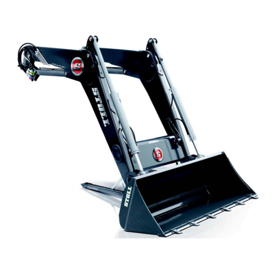
Summary of Contents for Stoll FS
- Page 1 Operating instructions Front loader ProfiLine Type FS, FS-rapid emptying, FZ, FZ-L Status: 06/2018 3468290 B58FZS 0000000078 EN 002...
- Page 2 Copyright © Wilhelm STOLL Maschinenfabrik GmbH Reproduction of these instructions, both completely and in excerpts, is only allowed with approval from Wilhelm STOLL Maschinenfabrik GmbH. Any infringement shall entail full compensation of damages and can be punishable by law. The original instructions were written in the German language.
-
Page 3: Table Of Contents
3.1 Structure of FS front loaders ........ - Page 4 4.5 Parallel motion (FZ, FZ-L) ..........45 4.6 Rapid traverse emptying (FS) and quick emptying (FZ-L)......46 4.7 Return-To-Level (FZ-L) .
- Page 5 11.4 Hydraulic diagram ........... . . 11.4.1 Hydraulic diagram FS and FS-rapid emptying ......
-
Page 6: About This Manual
Order the instructions through a dealer. Download instructions free of charge from the Internet at www.stoll-germany.com. Installation instructions The installation of the mounting kit as well as the hydraulic and electric equipment may only be performed by an authorised specialised workshop. -
Page 7: Use And Purpose Of The Operating Instructions
The operating instructions are valid only for the STOLL front loader ProfiLine, called "front loader" in the following or "FS" or "FZ" as the special versions. The front loader type can be found on the rating plate. The operating instructions covers all of the components and functions of the model. -
Page 8: Other Applicable Documents
ABOUT THIS MANUAL Other applicable documents In conjunction with these operating instructions, the following additional documents also apply: Operating instructions of the tractor Operating instructions for the respective implements Installation instructions for the respective mounting kit and front loader additional equipment When handling the front loader and for all service work, please also observe: ... -
Page 9: Nomenclature Of The Footer
ABOUT THIS MANUAL Moreover, stylised drawings are used. For better understanding, some of the figures are exemplary, simplified or with dismounted parts for better representation and explanation. Please observe the following: Dismounting is not always absolutely required for the respective description. ... -
Page 10: Safety
Immediate lethal danger or serious injuries. ⚠ WARNING Possible lethal danger or serious injuries. ⚠ CAUTION Possible slight injuries. NOTICE Damage to the implement or the surroundings. EC Conformity STOLL front loaders comply with Machine Directive 2006/42/EC. B58FZS 0000000078 EN 002... -
Page 11: Proper Use
The ProfiLine front loader is a mounted implement for agricultural and forestry tractors and is designed and intended solely for: Mounting on tractors with the front loader mounting kit approved by STOLL (see 1.1 Documentation overview), Use with work implements specified by STOLL, which are suitable for the respective loading work (see 6.5 Picking up and putting down the implement and operating instructions for the implement),... -
Page 12: Basic Safety Information
SAFETY Basic safety information The basic safety information comprises all safety measures grouped by theme and is applicable at all times. In addition, the information is presented as warning notices at the correspoding positions in these operating instructions. Basic dangers Mortal danger exists when persons are lifted or carried with the front loader. - Page 13 SAFETY Hydraulic dangers There is a risk of injury due to escaping hydraulic fluids under high pressure. Observe the safety stickers on the machine. Check the hydraulic couplings and lines for leaks before uncoupling. On tractors without a closed driver’s cab, mount tubes with splash guards. There is a risk of crushing when machine parts move uncontrollably due to entrapped air in the hydraulic system.
- Page 14 SAFETY Dangers during packaging and transport There is a risk of injury due to crushing, impacts or pinching if the front loader tips over or falls from the lifting gear. During all preparatory work, always ensure a secure stand of the machine. ...
- Page 15 SAFETY Dangers when picking up and putting down implements There is a risk of serious injury and lethal danger due to implements falling down or uncontrolled lowering of the front loader when unsuitable implements are used or if the used implements are overloaded. ...
- Page 16 SAFETY Dangers when operating the front loader There is a risk of serious injury or lethal danger due to tipping of the tractor when working on slopes, when going around bends, when the load on the rear axle is too low, and when driving into the bulk to be lifted at a skewed angle.
- Page 17 SAFETY Dangers due to falling loads There is mortal danger due to raised loads falling down on the driver's seat. There is a particularly high risk when lifting pallets or bales above the driver's cab and when working on slopes. Even the standard protection systems (roll-over protection structure ROPS, falling objects protective structures FOPS) do not provide fully adequate protection.
-
Page 18: Danger Zones
SAFETY Danger zones On and around the front loader, there are the following areas with increased risk to safety of the operator or safety of other persons: B081 Fig. 3 Top view (from above) Legend Work area (yellow) Outer danger zones (hatched in orange) Inner danger zones (red) Danger zone Description... -
Page 19: Adhesive Safety Label
Information on the operation of Comfort-Drive on the cross tube Information for crane transport above, below or next to the hole for the hook (on the deviation triangle on FZ front loaders, on the frame on FS front loaders) Sticker for safe manual implement locking, on the locking plug... - Page 20 SAFETY Description of the safety sticker The numbering corresponds to the positions on the front loader (see Position of the safety sticker on the front loader). 3441830b 3449070c B07A Fig. 5 Safety sticker position 1-5 B58FZS 0000000078 EN 002...
- Page 21 SAFETY Position Description Re-tighten all the fixing screws on the mounting kit after the first 5 hours of operation. Keep a safe distance away from electrical lines. Do not stack several loads on top of each other. Only use suitable implement to prevent the load from falling down. Increased risk of tilting when the front loader is raised.
- Page 22 SAFETY B07B Fig. 6 Safety sticker position 6-13 B58FZS 0000000078 EN 002...
- Page 23 SAFETY Position Description Instructions for mounting of the front loader. Instructions for dismounting of the front loader. The front loader is lowered when the Comfort Drive is switched on. Lever position to switch on the Comfort Drive. Lever position to switch off the Comfort Drive. Mounting points for crane transport of the front loader.
-
Page 24: Personnel Requirements
SAFETY 2.11 Personnel requirements In the operating instructions, a distinction is made between the following persons: Operators Qualified personnel Specialised tradesmen All person groups must have read and understood the operating instructions. The table lists the other respective qualifications and responsibilities. -
Page 25: Behaviour In Case Of Emergency
SAFETY 2.12 Behaviour in case of emergency Initiate the following measures to avoid further damage in cases of emergency: (1) Secure the accident site correctly. (2) Provide first aid (if necessary). (3) Call rescue workers, describe the situation briefly and concisely. Wait for feedback. (4) Inform the employer or operator. -
Page 26: Structure
STRUCTURE Structure Structure of FS front loaders FS front loaders are composed of the following main components: B065 Fig. 7 FS front loader B58FZS 0000000078 EN 002... - Page 27 STRUCTURE Legend Pillars (drive-in system) Lifting arm (base frame) Lifting cylinder: hydraulic cylinder for lifting and lowering Upper support for the implement position indicator Implement cylinders: hydraulic cylinders for dumping and scooping (differential cylinders) Parking supports Rating plate Lever mechanism dumping/scooping Euro change frame (implement support) Implement locking mechanism Cap for hydraulic and electrical distribution and additional equipment...
-
Page 28: Structure Of Fz Front Loaders
STRUCTURE Structure of FZ front loaders FZ front loaders are additionally equipped with parallel motion and are composed of the following main components: B064 Fig. 8 FZ front loader B58FZS 0000000078 EN 002... - Page 29 STRUCTURE Legend Pillars (drive-in system) Lifting arm (base frame) Lifting cylinder: hydraulic cylinder for lifting and lowering Deviation triangle of the parallel motion Indicator for implement position Implement cylinder: hydraulic cylinder for dumping and scooping (synchronised cylinder) Parking supports Rating plate Lever mechanism dumping/scooping Euro change frame (implement support) Implement locking mechanism...
-
Page 30: Equipment Variations
STRUCTURE Equipment variations The table shows the different equipment variations for FS and FZ front loaders: Equipment Front loader FS-rapid FZ-L emptying Basic equipment Parallel motion (mechanical) ─ ─ ● ● Change frame Euro ● ● ● ● ○ ○... -
Page 31: Attaching It To The Tractor
STRUCTURE Attaching it to the tractor The front loader is attached to the tractor using the mounting kit for tractors. The mounting kit consists of the following components: B06E Fig. 9 Mounting kit for tractors Legend Front guard left and right Mounting parts left and right Mountings/catch hooks The components remain permanently mounted on the tractor. -
Page 32: Change Frame
The change frame is a fixed component of the front loader. The different types are designed and adapted for the mounting of standardised implements of this type. As a matter of principle, the following change frames are available for FS and FZ 8 to 80.1 front loaders: ... -
Page 33: Sms Change Frame
STRUCTURE 3.5.2 SMS change frame These change frames are installed on FS and FZ 8 to 80.1 front loaders. The implement is hinged on the top cross bar and is secured with the locking mechanism. Its function is similar to that of the Euro change frame. -
Page 34: Euro-Alö3 Combi Change Frame
STRUCTURE 3.5.4 Euro-Alö3 Combi change frame These change frames are installed on FS and FZ 8 to 80.1 front loaders. They are intended for mounting implements complying with the Euro standard as well as the Alö3 standard. Euro implements are hinged onto the outer pins. -
Page 35: Skid-Steer Change Frame
Reinforced Euro change frame (FZ 100) The structure of this change frame is similar to the FS and FZ 8 to 80.1 Euro change frame. However, they are designed for higher loads and are always equipped with a hydraulic implement locking mechanism (see 4.1.2 Hydraulic... -
Page 36: Hydraulic Lines
STRUCTURE Hydraulic lines ⚠ CAUTION There is a risk of injury due to escaping hydraulic fluids! If the hydraulic lines are not depressurized before the coupling procedures, oil can spray out and injure the skin or other body parts (e.g. eyes). ... -
Page 37: Multiple Coupling Hydro-Fix
STRUCTURE 3.7.2 Multiple coupling Hydro-Fix As an option, the front loader can be equipped with the Hydro-Fix coupling. This enables simultaneous connection of all hydraulic lines with the couplings. The Hydro-Fix upper part is located on the hydraulic lines of the front loader. The Hydro-Fix lower part is located on the right-side mounting part for the tractor. -
Page 38: Functions
FUNCTIONS Functions Implement locking mechanism 4.1.1 Mechanical implement locking mechanism Euro, SMS and Combi change frames ⚠ WARNING Risk of injury due to implements falling down! The implement may fall down if the implement locking mechanism is open or not locked correctly. This can cause serious injury to persons standing in the surrounding area. - Page 39 FUNCTIONS The mechanical implement locking mechanism on Euro, SMS and Combi change frames is actuated manually. The implement is hinged with its hooks on the top cross bar on the change frame. Below, the implement rests on the bottom cross bar.
-
Page 40: Hydraulic Implement Locking Mechanism - Hydro-Lock
The hydraulic implement locking mechanism must only be installed by a specialist workshop. Only use switches that are approved by STOLL. Set the implement on the ground or on a safe support before using the implement locking function. -
Page 41: Basic Functions
FUNCTIONS Basic functions ⚠ DANGER Lethal danger due to loads falling down from front loaders without parallel motion! On front loaders without parallel motion, the implement tilts to the rear when lifting. As a result, the load can fall on the driver and cause lethal injuries. ... - Page 42 FUNCTIONS Lowering The 2 lifting cylinders are retracted and thus lower the lifting arm and the implement. Without parallel motion, the angle between the lifting arm and the implement remains constant so that the implement changes its orientation. With parallel motion, the angle between the lifting arm and the implement changes so that the implement maintains its original orientation.
- Page 43 FUNCTIONS Dumping The 2 implement cylinders are extended and thus swivel the implement downwards. The load is dumped out. B01M Fig. 26 Dumping function Legend Implement cylinders on the left and right Implement B58FZS 0000000078 EN 002...
-
Page 44: Float Position
The activation of the float position must be ruled out through the assembly on FS front loaders. If this is not the case, work with the front loader must be stopped immediately and the specialist workshop must be contacted, to have the float position deactivated for the scooping and dumping functions. -
Page 45: Lifting Arm Float Position
Activating the implement float position: (1) Lower the front loader close to the ground. (2) Move the operating lever to the right and press button T2 (green) (see 6.1.4 STOLL Pro Control). The float position is activated. B58FZS 0000000078 EN 002... -
Page 46: Indicator For Implement Position
FUNCTIONS Indicator for implement position The indicator for the implement position is located on the left implement cylinder. It allows the horizontal position of the implement to be read from the driver's seat. The rod is attached on the lower bearing pin and runs through the tube, which is attached to the upper bearing pin with the support. -
Page 47: Rapid Traverse Emptying (Fs) And Quick Emptying (Fz-L)
FUNCTIONS Rapid traverse emptying (FS) and quick emptying (FZ-L) ⚠ CAUTION Possible risk of accidents due to improper use of the rapid emptying! If the rapid emptying is actuated outside of a dumping process, it can cause a strong pressure drop in the hydraulic system. -
Page 48: Return-To-Level (Fz-L)
FUNCTIONS Return-To-Level (FZ-L) ⚠ WARNING Possible risk of injury due to uncontrolled lowering! Actuation of the RTL button while dumping causes the front loader to be lowered. Moreover, when dumping with insufficient fluid supply, a vacuum can form in the implement cylinder, which also causes lowering of the front loader. -
Page 49: Anti-Lowering Guard
FUNCTIONS Setting the return-to-level position: (1) Position the implement horizontally. (2) Lower the front loader to the ground. (3) Switch off the tractor. Apply the parking brake. Stop the engine. (4) Loosen the clamping screw. (5) Push the tube in the support until there is a space of about 10 mm between the top end of the rod and the top edge of the sensor. -
Page 50: Additional Functions
FUNCTIONS Additional functions 4.9.1 Additional control circuits ⚠ WARNING Risk of injury due to unexpected movement of the front loader or implement! If there is an electrical malfunction, operating elements can be temporarily or permanently out of function. As a result, it is possible that an unintended function is triggered instead of the selected implement functions (see 3rd control circuit and 4th control circuit). -
Page 51: Comfort Drive
FUNCTIONS 4th control circuit With a switch valve for the 4th control circuit, additional hydraulic implement functions are enabled. To operate the 4th control circuit, see 6.1.6 Switch/changeover switch. To operate the multiple coupling, see 3.7.2 Multiple coupling Hydro-Fix. B06V Fig. - Page 52 Indicator light Description Comfort Drive on Comfort Drive off The electro-hydraulic Comfort Drive can also be operated with STOLL Pro Control (see 6.1.4 STOLL Pro Control). B06Y Fig. 36 Switch-operated Comfort Drive Legend Switch position ON...
-
Page 53: Lowering Throttle
FUNCTIONS 4.9.3 Lowering throttle ⚠ WARNING Possible material damage due to overloading! The front loader can be lowered unevenly and be distorted when the two lowering throttles are not adjusted in the same way, and can cause personal injury. Set both lowering throttles to the same values. The lowering throttle is used to set the lowering speed of the front loader. -
Page 54: Start-Up
Operating the hydraulic couplings Is the electric cable of the front loader connected? Are the front loader locking mechanisms positioned correctly? Section 5.4.1 Adjusting the FS and FZ 8 to 50 front loader locking mechanism, Section 5.4.2 Adjusting the "Double locking mechanism"... -
Page 55: Preparations
START-UP Checks See also Completed After mounting Are the parking supports folded away and secured? Section 6.2 Operating the parking supports Is the front loader locking mechanism locked properly? Section 8.2.3 Service instructions for front loader locking mechanism Is the locking mechanism for the implement locked properly? Section 4.1 Implement locking mechanism... -
Page 56: Ballasting
START-UP 5.3.2 Ballasting ⚠ WARNING Serious injury due to the machine falling over! When working with the front loader without rear counterweights, the tractor can tip over and cause injury to the driver and persons in the surroundings. Moreover, there is the risk of overloading the front axle of the tractor. - Page 57 START-UP The formula to precisely determine the rear weight is specified in DIN EN 12525:2000-A2: Weight of the tractor in kg (incl. front loader and change frame without counterweight) Weight of the counterweight in kg Weight of the implement in kg (incl.
-
Page 58: Adjusting The Front Loader Locking Mechanism
On new front loaders, re-tighten the locking mechanism after the first hours of operation in order to compensate for any loosening caused by smoothing of the surfaces. 5.4.1 Adjusting the FS and FZ 8 to 50 front loader locking mechanism Adjusting the front loader locking mechanism: Open-ended spanner 24 mm WAF ... - Page 59 START-UP (2) Guide the open-ended spanner through the guide slot of the lever. B06C Fig. 43 Attaching the implement Legend Open-ended spanner Guide slot Ratchet (3) Loosen the locknut. (4) Adjust the clamping wedge with the screw. (5) Tighten the locknut. (6) Check the front loader locking mechanism.
-
Page 60: Mechanism
START-UP 5.4.2 Adjusting the "Double locking mechanism" FZ 50 to 100 front loader locking mechanism On the FZ 50 front loader, the double locking mechanism is installed as an option. Adjusting the front loader locking mechanism: Open-ended spanner 30 mm WAF ... - Page 61 START-UP (3) Close the front loader locking mechanism. Push the lever down. (4) Guide the socket wrench through the grommet to the screw. B080 Fig. 47 Guiding the socket wrench through to the screw Legend Socket wrench Lever (5) Unscrew the screw. ...
-
Page 62: Mounting The Front Loader
START-UP Mounting the front loader ⚠ WARNING Risk of injury due to uncontrolled movements! Uncontrolled movements of the front loader can cause injury to persons assisting in the surrounding area. Only mount the front loader when nobody is standing the the danger area (see 2.8 Danger zones). ... - Page 63 START-UP (3) Switch off the tractor. Apply the parking brake. Stop the engine. Depressurize the hydraulic system. To do so, move all of the operating levers to the end position. (4) Connect the hydraulic lines of the front loader (see 6.3 Operating the hydraulic couplings).
-
Page 64: Aligning The Front Loader For Mounting
START-UP Aligning the front loader for mounting ⚠ WARNING Risk of injury and accident when the front loader is not locked correctly! When the front loader locking mechanism is not adjusted correctly, the front loader can slip out of the mounting and cause accidents or personal injury. -
Page 65: Operation
The activation of the float position must be ruled out through the assembly on FS front loaders. If this is not the case, work with the front loader must be stopped immediately and the specialist workshop must be contacted, to have the float position deactivated for the scooping and dumping functions. - Page 66 OPERATION Depending on the equipment of the tractor, different operating levers can be installed for the front loader. In most cases, it is a cross lever or a joystick. On some tractors, there are 2 operating levers for the control of the front loader. The figures show a top view of the assignment for one operating lever (see Fig.
-
Page 67: Tractor's Own Operating Lever
Additional function with changeover switch FS, FZ 3rd control circuit FS-rapid Rapid emptying 3rd control circuit 4.6 Rapid traverse emptying emptying (FS) and quick emptying (FZ-L) Operating lever with 2 buttons Button Front loader Function Additional function with changeover switch FS, FZ... -
Page 68: Stoll Base Control
6.1.3 STOLL Base Control The STOLL "Base Control" operating lever is a single-lever control unit with up to 3 push-button switches for additional functions of the front loader and as an option, 2 micro-buttons on the sides for tractor functions. - Page 69 FS, FZ 3rd control circuit FS-rapid Rapid emptying 3rd control circuit 4.6 Rapid traverse emptying emptying (FS) and quick emptying (FZ-L) FZ-L Quick emptying 3rd control circuit FZ-L Return-To-Level 4th control circuit Buttons D and E are intended for the additional tractor functions and therefore have a different assignment depending on the model and the customer requirements.
-
Page 70: Stoll Pro Control
Possible risk of injury due to the implement tipping over! On FS front loaders, the float position for the implement may not be activated for the scooping and dumping functions. This could cause the implement to tip over unintentionally to the rear. This may result in serious accidents. - Page 71 OPERATION Switching on and off Switching on: (1) Switch on the tractor ignition (start engine). LED L1 lights up. The controls are in standby mode. (2) Briefly press the membrane key S1. LED L1 is flashing. Depending on the programming, the flashing cycle can look different. The front loader can now be operated with the joystick.
- Page 72 OPERATION Working at half-speed For work that requires particularly careful handling of the load, you can reduce the speed of the front loader hydraulic system to half. Switching functions on and off: (1) Put Pro Control into standby mode (see "Switching on and off"). (2) Press and hold membrane key S2.
-
Page 73: Stoll Trac Control
OPERATION 6.1.5 STOLL Trac Control The STOLL "Trac Control" operating lever is a handle with integrated buttons. It can replace the tractor's own operating lever if it does not have enough integrated buttons. The control of the operating lever is the same as the basic controls in section 6.1.1 Basic controls... -
Page 74: Switch/Changeover Switch
Rapid emptying and quick emptying/3rd control circuit To prevent simultaneous use of rapid emptying and quick emptying (see 4.6 Rapid traverse emptying (FS) and quick emptying (FZ-L)) and functions of the 3rd control circuit (see 4.9.1 Additional control circuits), both functions are assigned to the same switch. -
Page 75: Comfort-Hydraulic
OPERATION 6.1.7 Comfort-Hydraulic ⚠ CAUTION Risk of injury and material damage due to accidental movement of the front loader! On tractors that have tractor management, the Comfort hydraulic system can cause accidental movements of the front loader. Check that the tractor does not have tractor management if it is equipped with a Comfort hydraulic system. -
Page 76: Operating The Parking Supports
OPERATION Operating the parking supports ⚠ CAUTION Risk of crushing by swivelling components! When folding the parking supports, limbs can be crushed. When folding the parking supports, do not reach between them and the lifting arm bar. The parking supports serve to safely put down the front loader. Locking struts allow adaptations to be made for putting down the front loader with different implements as well as on different surfaces. -
Page 77: Operating The Hydraulic Couplings
OPERATION Operating the hydraulic couplings 6.3.1 Operating the plug-in coupling Connecting plugs with couplings: (1) Remove the caps and wipe the coupling if necessary. (2) Insert the connector in the couplings. (3) Stick the caps together to prevent soiling. The plug-in couplings are connected. Disconnecting the plugs from the couplings: (1) Pull out the plugs from the couplings. -
Page 78: Operating Hydro-Fix
OPERATION 6.3.2 Operating Hydro-Fix ⚠ WARNING Risk of injury and material damage due to soiled hydraulic couplings! Hydro-Fix couplings that are not cleaned on a regular basis can result in plug parts not being correctly connected or parts of the Hydro-Fix being damaged when attempting to couple them. This can cause malfunctions of the hydraulic system. -
Page 79: Operating The Implement Locking Mechanism
OPERATION Operating the implement locking mechanism 6.4.1 Operating the mechanical implement locking mechanism on Euro, SMS and Combi change frames ⚠ WARNING Risk of injury due to implements falling down! The implement may fall down if the implement locking mechanism is open or not locked correctly. This can cause serious injury to persons standing in the surrounding area. - Page 80 OPERATION Check the implement locking mechanism: Check that the tip of the arrow on the sticker is aligned directly at the socket. Check that the locking pins engage correctly in the eyelets of the implement. B06P Fig. 67 Using the sticker to check the implement locking mechanism ...
-
Page 81: Frames
OPERATION 6.4.2 Operating the mechanical implement locking mechanism on skid-steer change frames ⚠ WARNING Risk of injury due to implements falling down! The implement may fall down if the implement locking mechanism is open or not locked correctly. This can cause serious injury to persons standing in the surrounding area. ... -
Page 82: Operating The Hydraulic Implement Locking Mechanism
The hydraulic implement locking mechanism must only be installed by a specialist workshop. Only use switches that are approved by STOLL. Set the implement on the ground or on a safe support before using the implement locking function. -
Page 83: Picking Up And Putting Down The Implement
OPERATION Picking up and putting down the implement ⚠ WARNING Risk of injury and material damage caused by falling loads or lowering front loader! With dumping implements that are long or protrude far to the front, the centre of gravity can shift and cause the pressure relief valve of the front loader to open by itself. -
Page 84: Picking Up Implements With Mechanical Implement Locking Mechanism On Euro
OPERATION 6.5.1 Picking up implements with mechanical implement locking mechanism on Euro, SMS and Combi change frames ⚠ WARNING Risk of injury and material damage due to implements falling down! The automatic locking mechanism only works up to a height of about 1.5 m. Implements not locked correctly may fall down and cause damage to the surroundings as well as injuries. - Page 85 OPERATION (4) Carefully drive the tractor forwards until the cross bar of the change frame touches the implement. B07P Fig. 76 Hooking in (5) Use the scooping function and drive forward a bit until the cross bar is hooked in. ...
-
Page 86: Picking Up Implements With Mechanical Implement Locking Mechanism On Skid
OPERATION 6.5.2 Picking up implements with mechanical implement locking mechanism on skid-steer change frames ⚠ WARNING Risk of injury due to implements falling down! The implement may fall down if the implement locking mechanism is open or not locked correctly. This can cause serious injury to persons standing in the surrounding area. - Page 87 OPERATION (5) Switch off the tractor. Switch off the engine. Apply the parking brake. (6) Close the implement locking mechanism manually (see 6.4.2 Operating the mechanical implement locking mechanism on skid-steer change frames). (7) If applicable, connect the hydraulic lines of the implement with the front loader B089 couplings.
-
Page 88: Picking Up Implements With A Hydraulic Implement Locking Mechanism
OPERATION 6.5.3 Picking up implements with a hydraulic implement locking mechanism ⚠ WARNING Risk of injury due to implements falling down! The implement may fall down if the implement locking mechanism is open or not locked correctly. This can cause serious injury to persons standing in the surrounding area. ... -
Page 89: Putting Down The Implement
OPERATION 6.5.4 Putting down the implement Putting down the implement: (1) Lower the front loader and the implement horizontally on the ground or a secure rack. (2) Switch off the tractor. Apply the parking brake. Stop the engine. ... -
Page 90: Levelling In Reverse
OPERATION Levelling in reverse NOTICE Material damage due to improper levelling! If the front loader is not correctly used for levelling, the machine can be overloaded and damaged. Only perform levelling work with bucket implements. Level only with the front edge of the bucket. ... -
Page 91: Driving On Roads
OPERATION Driving on roads ⚠ WARNING Serious risk of accidents and injury due to loads falling down! When driving on roads, serious accidents and injuries can be inflicted on other road users due to loads falling down. Only drive on roads without a load. ⚠... -
Page 92: Activating And Deactivating The Road Operation Lock
STOLL Base Control To activate the road operation lock: (1) Lock the operating lever (see 6.1.3 STOLL Base Control) in the zero position. The road operation lock is activated. Accidental actuation of the front loader is no longer possible. -
Page 93: Parking The Tractor With The Front Loader
OPERATION Parking the tractor with the front loader ⚠ WARNING Possible risk of injury due to lowering of the front loader! The front loader is lowered over time by the drop in pressure in the hydraulic system. This can result in damage and accidents. -
Page 94: Troubleshooting
If these points do not resolve the problem, the following table will help to localize and correct the fault. Incorrect repairs can lead to safety risks. That is why the repair work must only be carried out by suitably qualified personnel! STOLL recommends that the repair work be performed at a specialised workshop. B58FZS 0000000078 EN 002... - Page 95 TROUBLESHOOTING Description of the fault Cause Rectifying the fault It is difficult to move the operating Bowden cables are stiff. Check the attachment and routing of the lever (stiff). Bowden cables and if they are stuck anywhere. If necessary, oil or replace the Bowden cables.
- Page 96 The front loader rocks when Lowering speed too high. Reduce the lowering speed. lowering the load. Unstable implement on FS rapid Rapid emptying activated without dumping. Only activate the rapid emptying during the emptying front loaders (implement This causes a vacuum in the hydraulic dumping process.
-
Page 97: Servicing
SERVICING Servicing ⚠ WARNING Serious risk of injury due to uncontrolled lowering of the front loader! During service and repair work, a raised front loader can be lowered unexpectedly and crush and injure nearby persons. Only perform maintenance work when the front loader is completely lowered. ⚠... -
Page 98: Cleaning And Care
SERVICING Cleaning and care NOTICE Possible material damage due to unsuitable cleaning agents! Unsuitable cleaning agents can damage surfaces and safety devices as well as destroy seals. Only use cleaning agents that are compatible with the machine surfaces and seal materials. Clean the front loader with water and a mild cleaning agent. - Page 99 SERVICING Lubrication points on FS and FZ front loaders The FS front loader has 9 lubrication points on each side: B068 Fig. 91 Lubrication points on the FS B58FZS 0000000078 EN 002...
-
Page 100: Lubrication Schedule
SERVICING The FZ front loader has 12 lubrication points on each side: B066 Fig. 92 Lubrication points on the FZ The grease nipple at Position 1 can only be reached by slightly lifting the front loader and putting it down on the tip of the implement. -
Page 101: Service
SERVICING Service ⚠ WARNING Lethal danger and material damage due to lack of service! Service tasks deferred or carried out incorrectly impair the safety of the front loader. Only have service carried out by authorised personnel. Only have visible defects repaired by trained qualified personnel. ... -
Page 102: Service Instructions For Front Loader Mountings
SERVICING 8.2.2 Service instructions for front loader mountings ⚠ WARNING Risk of serious injury due to the front loader breaking off! In cases of strong wear of the catch hook, the front loader can break off of the mounting part and thus cause serious injury to the driver or persons standing nearby. -
Page 103: Service Instructions For Front Loader Locking Mechanism
SERVICING 8.2.3 Service instructions for front loader locking mechanism Checking the FS and FZ 8 to 50 front loader locking mechanism Checking the front loader locking mechanism: (1) Completely open the front loader locking mechanism. (2) Close the front loader locking mechanism. -
Page 104: Service Instructions For Comfort Drive
SERVICING (2) Blow out the front loader locking mechanism with compressed air. (3) Pay attention to the gap between the disc springs and the turning lock. The clamping wedge is tensioned to the maximum when the gap virtually disappears or the disc spring is flat. -
Page 105: Service Instructions For Oil Changes
SERVICING 8.2.6 Service instructions for oil changes The front loader is supplied by the oil circulation of the tractor. Observe the oil change intervals specified for the tractor. Before performing an oil change, lower the front loader onto the ground. ... -
Page 106: Decommissioning
DECOMMISSIONING Decommissioning Temporary decommissioning ⚠ WARNING Risk of injury due to lacking stability! If the front loader is not correctly and safely parked, it can tip over and injure persons nearby. Only park the front loader with a mounted implement that weighs at least 70 kg. ... -
Page 107: Recommissioning
DECOMMISSIONING (6) Using the lowering function, release the front loader pins from the catch hooks. (7) Switch off the tractor. Apply the parking brake. Stop the engine. Depressurize the hydraulic system. To do so, move all of the operating levers to the end position. -
Page 108: Final Decommissioning And Disposal
DECOMMISSIONING Final decommissioning and disposal NOTICE Environmental damage due to improper disposal! The front loader contains operating materials as well as electrical and hydraulic components that need to be disposed of separately. Improper disposal can harm the environment. Observe the national and local regulations and environmental legislation for the disposal. ... -
Page 109: Spare Parts And Customer Service
The use of non-approved spare parts can impair the safety of the front loader and results in expiry of the operating permit. Only use original spare parts or those approved by STOLL. Original spare parts and fitting accessories are listed in separate spare part lists. -
Page 110: Technical Specifications
TECHNICAL SPECIFICATIONS Technical specifications 11.1 Dimensions and weights Front loader Nominal width Lifting arm length Nominal lifting force Weight [mm] [mm] [daN] [kg] FS 8 2300 1660 FZ 8 2300 1660 FS 10 2500 1720 FZ 10 2500 1720 FS 20... -
Page 111: Tightening Torque For Screws
CONTENTS 11.3 Tightening torque for screws Tightening torque for screws Strength category Thread 10.9 12.9 lb-ft lb-ft lb-ft M8x1 M10x1.25 M12x1.5 M12x1.25 M14x1.5 M16x1.5 M18x2 M18x1.5 M20x2 M20x1.5 M22x2 M22x1.5 1022 1017 1190 M24x2 1095 1282 1176 1496 1103 1750 1291 M27x2 1262... -
Page 112: Hydraulic Diagram
11.4.1 Hydraulic diagram FS and FS-rapid emptying 210 bar 210 bar 150 bar S2 / S3b B04G Fig. 102 Hydraulic diagram FS and FS-rapid emptying Legend F1, S1 4th control circuit (optional) F2, S2 3rd control circuit (optional) F3b, S3b... -
Page 113: Hydraulics Diagram Fz And Fz-L
CONTENTS 11.4.2 Hydraulics diagram FZ and FZ-L 210 bar 210 bar 150 bar S2 / S3a B04F Fig. 103 Hydraulics diagram FZ and FZ-L Legend F1, S1 4th control circuit (optional) F2, S2 3rd control circuit (optional) F3a, S3a Quick emptying (only FZ-L) F4b, S4b Return To Level (only FZ-L) F5, S5... -
Page 114: Electric Circuit Diagram
Suppressor diodes: reduce disruptions caused by the solenoid valves. Depending on the equipment, the suppressor diodes on FS front loaders are used on terminals 1, 2 and/or 3, and with FZ front loaders, they are on terminals 1, 2 and/or 4. -
Page 115: Arrangement Of The Hydraulic Valves For Additional Functions
Hydraulic valve for 4th control circuit Hydraulic valve for 3rd control circuit Hydraulic valve for rapid emptying (on FS-rapid emptying) or quick emptying (on FZ-L) Hydraulic valve for re-scooping or return-to-level (on FZ-L) Hydraulic valve for electrically controlled Comfort Drive... -
Page 116: Declaration Of Conformity
Directive 2014/68/EU on the provision of pressure equipment on the market. The technical documentation was produced according to Annexe VII A of Directive 2006/42/EC, and is the responsibility of the development manager at Wilhelm STOLL Maschinenfabrik GmbH, Bahnhofstrasse 21, D-38268 Lengede. - Page 117 DECLARATION OF CONFORMITY The design and manufacturing of the front loader observed the following harmonised standards that are also published in the EU official gazette: Harmonised Date Title of the standard standards DIN EN ISO 4254-1 2016-09 Agricultural machinery - Safety - Part 1: General requirements DIN EN ISO 4413 2011-04 Hydraulic fluid power –...
-
Page 118: Index
Lubrication points on the catch hooks. . 97 Dangers during packaging and Lubrication points on the FS ..98 transport ......13 Lubrication points on the FZ .. - Page 119 Spare parts ......108 Structure of FS front loaders...25 Structure of FZ front loaders ...27 Switching on Pro Control .
- Page 120 Address of the dealer Stick or write down the serial number here Wilhelm STOLL Maschinenfabrik GmbH STOLL on the Internet: PO box 1181, 38266 Lengede www.stoll-germany.com Bahnhofstr. 21, 38268 Lengede www.facebook.com\STOLLFrontloader Phone: +49 (0) 53 44/20 0 www.youtube.com\STOLLFrontloader Fax: +49 (0) 53 44/20 182 E-mail: info@stoll-germany.com...
Need help?
Do you have a question about the FS and is the answer not in the manual?
Questions and answers