Table of Contents
Advertisement
Quick Links
Plastic Volute Casing
Centrifugal Pump
Original Operating Manual
Version
BA-2015.12.16 EN
Print-No.
300 486
TR MA DE Rev001
Series
SHB
ASV Stübbe GmbH & Co. KG
Hollwieser Strasse 5
32602 Vlotho
Germany
Phone: +49 (0)5733-799-0
Fax: +49 (0)5733-799-5000
Email: contact@asv-stuebbe.de
Internet: www.asv-stuebbe.com
We reserve the right to make technical changes.
Read carefully before use.
Save for future use.
Advertisement
Table of Contents
Troubleshooting

Summary of Contents for Stubbe SHB Series
- Page 1 Plastic Volute Casing Centrifugal Pump Original Operating Manual Series Version BA-2015.12.16 EN ASV Stübbe GmbH & Co. KG Print-No. 300 486 Hollwieser Strasse 5 TR MA DE Rev001 32602 Vlotho Germany Phone: +49 (0)5733-799-0 Fax: +49 (0)5733-799-5000 Email: contact@asv-stuebbe.de Internet: www.asv-stuebbe.com We reserve the right to make technical changes.
-
Page 2: Table Of Contents
Table of contents Table of contents ....... 5 Connecting the pipes . - Page 3 Table of contents 9.2.4 Sound pressure level ......34 9.2.5 Flange tightening torques ....34 9.2.6 Tightening torques of casing screws .
- Page 4 Table of contents List of figures List of tables Fig. 1 Type plate (example) ......9 Tab. 1 Other applicable documents, purpose and where found .
-
Page 5: About This Document
About this document About this document Other applicable documents This manual • Is part of the equipment • Applies to the aforementioned pump series ATEX additional manual (300 365) • Describes safe and appropriate operation during all oper- • Additional instructions for use in ating phases explosive atmospheres Target groups... -
Page 6: Warnings And Symbols
About this document Warnings and symbols Symbol Meaning • Immediate acute risk • Death, serious bodily harm • Potentially acute risk • Death, serious bodily harm • Potentially hazardous situation • Minor injury • Potentially hazardous situation • Material damage Safety warning sign Take note of all information highlighted by the safety warning... -
Page 7: Safety
Safety Safety The manufacturer does not accept any liability for any dam- • When using auxiliary plant systems: age caused by disregarding any sections of the entire doc- – Ensure compatibility of the operating medium with the umentation. product medium. –... -
Page 8: Operator's Obligations
Safety 2.2.2 Operator's obligations 2.2.3 Obligations of personnel • All directions given on the pump must be followed (and kept Safety-conscious operation legible), e.g. the arrow indicating the sense of rotation and • Only operate the pump if it is in perfect technical condition the markings for fluid connections. -
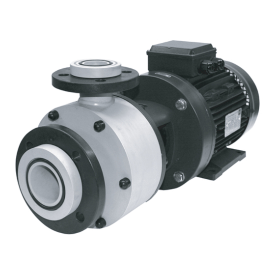
Page 9: Layout And Function
Layout and function Layout and function Labels Description • Non self-priming, modular-design, horizontal centrifugal 3.1.1 Type plate pump with mechanical seal • Self-priming if priming tank also installed ASV Stübbe GmbH & Co. KG Tel.: +49 (0) 57 33 / 79 9-0 Fabr. -
Page 10: Design
Layout and function Design Fig. 3 Design of SHB 15–80 to 25–125 Fig. 4 Design of SHB 32–125 to 100–200 Mechanical seal Impeller Coupling Discharge flange Shaft 10 Support foot Volute casing Pump mounting bracket Suction branch Motor BA-2015.12.16 EN 300 486... -
Page 11: Shaft Seals
Layout and function Shaft seals Blocking When blocking, the pressure of the sealing medium is greater Only one of the following shaft seals can be used. than the pressure of the pumped medium. The seal surfaces are lubricated by the sealing medium. 3.4.1 Mechanical seals Examples of use:... -
Page 12: Transport, Storage And Disposal
Transport, Storage and Disposal Transport, Storage and Disposal Transport 4.1.3 Lifting The user/owner is responsible for the transport of the DANGER pump. Death or limbs crushed as a result transported items Weight specifications (→ documents for the particular falling over. order) Use lifting gear appropriate for the total weight to be trans- ported. -
Page 13: Storage
Transport, Storage and Disposal Storage NOTE Material damage due to inappropriate storage! Store the pump properly. 1. Seal all openings with blind flanges, blind plugs or plastic covers. 2. Make sure the storage room meets the following condi- tions: – –... -
Page 14: Installation And Connection
Installation and connection Installation and connection For pumps in potentially explosive atmospheres (→ ATEX 5.1.3 Prepare foundation and surface additional manual). Aids, tools, materials: – Steel shims – Spirit level NOTE Installation options: Material damage due to distortion or passage of electrical –... -
Page 15: Attaching Pump Unit
Installation and connection Planning the pipes 3. Position the pump unit on the foundation. When doing so lower the anchor bolts into the prepared anchoring holes. Water hammers may damage the pump or the system. Plan the pipes and fittings as far as possible to prevent water hammers occurring. -
Page 16: Specifying Pipe Lengths
Installation and connection 5.3.3 Specifying pipe lengths 5.3.4 Provide self-priming container A self-priming container can be used to make the pump self-priming. > 2xDN > 1,5xDN Fig. 7 Straight pipe lengths in front and after the pumps (recommended) > 1,5xDN >... -
Page 17: Providing Safety And Control Devices (Recommended)
Installation and connection Connecting the pipes 5.3.7 Providing safety and control devices (recommended) Avoid contamination NOTE 1. Install filters in the suction pipe. Material damage due to excessive forces and torques on 2. Install a differential pressure gauge with contact manome- the pump. -
Page 18: Electrical Connection
Installation and connection Electrical connection DANGER Risk of death due to electric shock! All electrical work must be carried out by qualified electri- cians only. Before all work on the electrical system, disconnect the motor from the mains and secure against being switched back on again. -
Page 19: Operation
Operation Operation For pumps in potentially explosive atmospheres (→ ATEX 6.1.4 Check direction of rotation additional manual) DANGER Preparing for commissioning Danger to life from rotating parts. Use personal protective equipment when carrying out any 6.1.1 Checking downtimes work on the pump. Maintain an adequate distance from rotating parts. -
Page 20: Commissioning
Operation Commissioning 5. Once the motor has reached its nominal speed, open the pressure-side fitting slowly until the operating point is reached. 6.2.1 Switching on 6. Make sure temperature change is smaller than 5 K/min for Pump set up and connected properly pumps with hot fluids. -
Page 21: Restoring The Pump To Service
Operation Restoring the pump to service Take the following measures whenever the pump is shut down: 1. Complete steps commissioning (→ 6.2 Commissioning, Page 20). Pump is Action 2. If the pump is shut down for over 1 year, replace elastomer shut down Take measures appropriate for seals (O-rings, shaft sealing rings). -
Page 22: Maintenance
Maintenance Maintenance Maintenance Mechanical seals are subject to natural wear and tear which is heavily dependent on the particular operating For pumps in potentially explosive atmospheres (→ ATEX conditions concerned. It is therefore not possible to make additional manual). general statements about their service life. Trained service technicians are available for fitting and repair work. -
Page 23: Cleaning The Pump
Maintenance 7.2.3 Cleaning the pump WARNING Risk of injury during disassembly! NOTE Secure the pressure-side gate valve against accidental High water pressure or spray water can damage bearings! opening. Do not clean bearing areas with a water or steam jet. Depressurize the blocking pressure system, if available. -
Page 24: Dismantling Shb 15-80 To 25-125
Maintenance 7.3.2 Dismantling SHB 15–80 to 25–125 7.3.3 Dismantling SHB 32–125 to 100–200 Cross-sectional drawing: Cross-sectional drawing: 1. Remove protective caps (580.1). 1. Remove protective caps (580.1). 2. Unscrew hexagon-head bolts (901.5). 2. Unscrew hexagon-head bolts (901.5). 3. Remove volute casing (102.1) from housing cover (161.1). 3. -
Page 25: Installing
Maintenance Installing 2. Installing the pump: – in reverse order to the dismounting Install components concentrically and without tilting in Removing: accordance with the markings applied. (→ 7.3.2 Dismantling 15–80 25–125, Page 24). Apply graphite paste to metallic connections prior to (→... -
Page 26: Aligning Pump And Motor Shaft, Shb 15-80 To 25-125
Maintenance Aligning pump and motor shaft, 14. Push the casing cover (161.1) together with the impeller (230.1) onto the pump shaft (210.1). SHB 15–80 to 25–125 15. Insert the key (940.1) into the groove of the pump shaft Cross-sectional drawing: (→... -
Page 27: Aligning Pump And Motor Shaft, Shb 32-125 To 100-200
Maintenance Aligning pump and motor shaft, 14. If necessary, correct the run-out by striking the shaft care- fully with a rubber mallet. SHB 32-125 to 100-200 When doing so, take care not to damage the motor shaft Cross-sectional drawing: (→ 9.1.2 Drawing for SHM bearings and the pump shaft. -
Page 28: Troubleshooting
Troubleshooting Troubleshooting For pumps in potentially explosive atmospheres (→ ATEX additional manual). If faults occur which are not specified in the following table or cannot be traced back to the specified causes, please consult the manufacturer. Possible faults are identified by a fault number in the table below. - Page 29 Troubleshooting Fault number Remedy Cause – – – – – Intake / suction pipe contains trapped air Install fitting for venting. Adjust piping installation. – – – – Air is sucked in Seal source of problem. Air is being drawn in through the shaft Replace the seals.
-
Page 30: Troubleshooting List
Troubleshooting Fault number Remedy Cause – – – – – – System delivery head lower than pump Restrict pressure-side valve flow. delivery head Fit a smaller impeller. Reduce rotation speed. Use a smaller pump. – – – – Motor speed too high Compare the required motor speed with the specifications on the pump type plate. -
Page 31: Appendix
Appendix Appendix Replacement parts 9.1.1 Drawing for SHM 15–80 to 25–125 Not used on size 80 motor 300 486 BA-2015.12.16 EN... - Page 32 Appendix 9.1.2 Drawing for SHM 32–125 to 100–00 On size 90 motor: Stud bolt BA-2015.12.16 EN 300 486...
-
Page 33: Part No. And Description
Appendix 9.1.3 Part no. and description Part no. Designation 903.1 Plug screw Part no. Designation 903.4 Plug screw 102.1 Volute casing 904.1 Headless setscrew 153.1 Suction branch 904.2 Headless setscrew 156.1 Discharge flange 914.1 Hexagon head bolt 161.1 Housing cover 914.5 Cylinder screw 183.1... -
Page 34: Technical Specifications
Appendix Technical specifications 9.2.4 Sound pressure level Sound pressure level < 75 dB(A) Further technical data (→ Data sheet). Measuring conditions: • Distance to the pump: 1 m 9.2.1 Ambient conditions • Operation: free of cavitation Operation under any other ambient conditions should be agreed with the manufacturer. -
Page 35: Maintenance Plan
Appendix Maintenance plan Designation Interval Maintenance Pump assembly daily Check for increased noise development. Check for vibration. Check for raised motor temperature. Pay attention to increased current consumption of the motor. Check that the anchor bolts are correctly seated. Check for oxidation. Check for leaking pumped liquid. -
Page 36: Declaration Of Conformity In Accordance With Ec Machinery Directive
Appendix Declaration of conformity in accordance with EC machinery directive CE declaration of conformity We hereby declare under our sole responsibility that the products listed below Description Centrifugal pumps with mechanical seal NM, NMB, NMXH, SHB Solenoid pumps Eccentric pumps Type F, Type L Sump pumps ET, ETL, ETLB...
Need help?
Do you have a question about the SHB Series and is the answer not in the manual?
Questions and answers