Table of Contents

Related Manuals for Life technologies EVOS FL

Summary of Contents for Life technologies EVOS FL
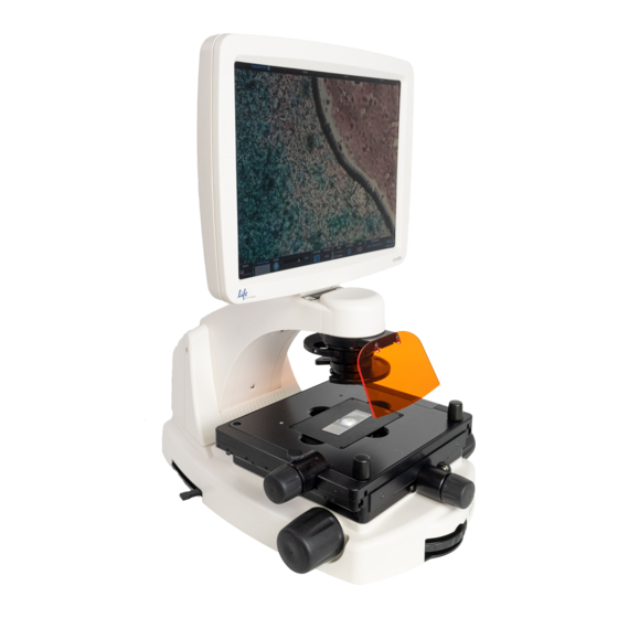
- Page 1 user guide EVOS ® EVOS FL Color ® imaging systems for Fluorescence Transmitted Light Applications Catalog Numbers AMF4300, AMEFC4300 Publication Number MAN0007988 Revision 1.0 For Research Use Only. Not for use in diagnostic procedures.
- Page 2 PURPOSE, OR NON-INFRINGEMENT. TO THE EXTENT ALLOWED BY LAW, IN NO EVENT SHALL LIFE TECHNOLOGIES AND/OR ITS AFFILIATE(S) BE LIABLE, WHETHER IN CONTRACT, TORT, WARRANTY, OR UNDER ANY STATUTE OR ON ANY OTHER BASIS FOR SPECIAL, INCIDENTAL, INDIRECT, PUNITIVE, MULTIPLE OR CONSEQUENTIAL DAMAGES IN CONNECTION WITH OR ARISING FROM THIS DOCUMENT, INCLUDING BUT NOT LIMITED TO THE USE THEREOF.
-
Page 3: Table Of Contents
Contents About this Guide ............................. 5 1. Quick Reference Diagrams ..................6 Hardware Controls ............................6 Hardware Glossary ............................7 User Interface (UI) Controls ........................... 8 Software Glossary ............................9 Specifications ..............................11 2. Installing the EVOS ® FL Imaging System ............... 12 Standard Items Included .......................... - Page 4 Appendix A: Troubleshooting..................40 Image Quality Issues ............................. 40 Software Interface Issues ..........................41 Mechanical Issues ............................42 Appendix B: Safety ...................... 43 Safety Conventions Used in this Document ....................44 Symbols on Instruments ..........................45 Safety Labels on Instruments ........................47 General Instrument Safety ...........................
-
Page 5: About This Guide
(for example, imaging stained tissue samples). Safety Alert Words Four safety alert words appear in Life Technologies user documentation at points in the document where you need to be aware of relevant hazards. Each alert word—IMPORTANT, CAUTION, WARNING, DANGER—implies a particular level of observation or action, as defined below: IMPORTANT! –... -
Page 6: Quick Reference Diagrams
1. Quick Reference Diagrams Hardware Controls Figure 1 FL footprint Power Input Jack Y-Axis Stage Brake Power Switch Focusing Knobs USB and DVI Ports Objective Selection Wheel Coarse Stage Positioning Knobs Light Cube Selection Lever Stage X-Axis Knob Phase Annuli Selector X-Axis Stage Brake Condenser Slider Slot Stage Y-Axis Knob... -
Page 7: Hardware Glossary
Hardware Glossary Power Input Jack Plug the power adapter into the power input jack. Power Switch Set the power switch to “—” to turn the instrument on or “O” to turn it off. USB and DVI Ports Plug the mouse and flash drive into the USB ports. Use the DVI port for digital output to a projector or other display. -
Page 8: User Interface (Ui) Controls
User Interface (UI) Controls UI controls are software-driven controls for using the FL menu system. Note: Periodically, Life Technologies adds functionality and other improvements to the EVOS ® user interface. We recommend keeping your ® EVOS FL Imaging System up to date with the latest software. If you have any questions about software updates, contact your local distributor. -
Page 9: Software Glossary
Software Glossary Channel Indicator Bar The channel indicator bar highlights the active channel (i.e., the light channel that is currently selected). Login Button The Login button allows for logging in and creating or changing user profiles. This button also displays the current user profile (for example, “Guest”). Control Bar Tabs Find &... - Page 10 Settings Control Opens the Settings dialog box. Button Note: See “Optional Settings” (page 30) for a complete overview of the settings. Save Image Button Use to save the onscreen image to a USB flash drive or network folder. The USB icon turns from red to green once the image has been saved.
-
Page 11: Specifications
Specifications Optics Infinity-corrected optical system; RMS-threaded objectives with 45 mm parfocal distance Objectives included vary per order. Contact Technical Support (see page 54) for a full list Objectives of objectives supported. Objective 5-position; front-mounted control Turret Light cubes included vary per order. Specifications for our most popular light cubes are listed below. -
Page 12: Installing The Evos ® Fl Imaging System
2. Installing the EVOS ® FL Imaging System Standard Items Included Before setting up the EVOS ® FL Imaging System, unpack the unit and accessories and verify all parts are present. Contact your distributor if anything is missing. Note: If you do not have your distributor information, contact Technical Support (see page 54). -
Page 13: Unpacking
Unpacking Note: All steps MUST be completed PRIOR to using the instrument. To remove the instrument from the packaging, lift the instrument by grasping it firmly with both hands under the support and place on a level surface away from vibrations from other pieces of equipment. -
Page 14: Operating Environment
Operating Environment • Allow at least 5 cm (2 in) free space at the back of the instrument to allow for proper ventilation and to prevent overheating of electronic components. • Operating temperature range: 4°–32°C (40°–90°F). • Relative humidity range: 30–90%. •... -
Page 15: Pins/Locks And Power Supply
Pins/Locks and Power Supply Now that you have unpacked the unit and accessories and verified all parts are present, it is time to set up the EVOS ® FL Imaging System. Follow all steps prior to powering on for the first time. Stage Lock Pin Note: Before using the mechanical stage for the first time, you must remove the stage lock pin from the back right-hand corner of the stage... -
Page 16: Ports And Shields
Ports and Shields USB Ports Plug the mouse and the USB flash drive into the USB ports located on the bottom right of the support arm. You may also plug in a USB keyboard (not included) for text input. DVI Output Port Note: A DVI port is available for output to a projector or other display (DVI cable not included). -
Page 17: Basic Operations
3. Basic Operations Note: Before using the mechanical stage for the first time, you must remove the stage lock pin from the back right-hand corner of the stage plate. For information about adding optional LED light cubes, see “Changing LED Light Cubes” (page 37). Brightfield/Phase Operations Set the magnification using the objective selection wheel on the front of the instrument. - Page 18 Note: The instrument is pre-configured with an overexposed pixel feature. Overexposed pixels will appear red, to obtain the maximum level of brightness without any overexposed areas, dim the illumination until the red highlights disappear. To disable this feature, go to the Basic Tab, found under the settings menu (Figure 9).
-
Page 19: Fluorescence Operations
Fluorescence Operations Set the magnification using the objective selection wheel on the front of the instrument. Move light cube selection lever until the active fluorescent channel on screen reflects the desired light cube (i.e., “GFP”). Place the light shield box on the stage, over the sample. This is important for optimal image quality. -
Page 20: Advanced Operations
4. Advanced Operations Transfection Note: See “Working with Images” (page Error! Bookmark not defined.) for more information. Choose a light cube, focus on the sample, and adjust the lighting. See “Fluorescence Operations” (page 19) for detailed instructions, if needed. Open the Toolbar and expand the Transfection tool (Figure 10). Note: The “Pause after first image”... -
Page 21: Time Lapse
Time Lapse Note: The Time Lapse feature allows you program the instrument to record time lapse images. To create a video (.avi) file, select the Write Video File option prior to running the time lapse session (lower left corner of the Time Lapse Tool bar window (Figure 11). Figure 11 Toolbar: Time Lapse Setting Up Time Note: After parameters have been selected, the software will calculate the... - Page 22 Saving Time Lapse Click the Browse button to select the destination. Files Highlight the desired folder in the Browse popup and click OK. Note: If there is no USB flash drive or network connection in place, a warning message will appear. Insert a USB flash drive, and then click the Cancel button to clear the message.
-
Page 23: Working With Images
5. Working with Images Live/Captured Zoom and Scalebar Option Live/Captured Double-click the area of interest in the image onscreen. A 2x zoomed image, centered on the point clicked, will appear. Imagery and Zoom Feature Right-click anywhere on the image to restore the view to the default magnification. -
Page 24: Cell Counting
Cell Counting The Count tool streamlines cell counting by marking items with up to 6 labels onscreen. As you tag items, the system will keep a running tally of counts with percentages for each label assigned. Document your results simply by saving the tagged image, with the Count tool displaying the totals. - Page 25 Note: To use Digital Zoom while counting cells, first suspend the Count tool, then select the Hide Tags setting. When the tags are hidden, use the left mouse button to double-click and Zoom as described in “Live/Captured Zoom and Scalebar Option” (page 23). After zooming, reactivate the Count tool by deselecting Hide Tags setting.
-
Page 26: Saving
Saving Basic Saving Note: If there is no USB flash drive or network connection in place, a warning message will appear. Insert a USB flash drive, then click the Cancel button to clear the message. After capturing your image (see “Basic Operations” on page 17), click the Save button. - Page 27 Helpful Tips • Click in the Comment text field to enter a comment and date. • The date button can be used within a file or folder name. Clicking the Date button anywhere within a text field will automatically insert the current date (MM-DD-YYYY) wherever the cursor is in that field.
- Page 28 Note: The color camera version displays the QuickSave option in all tabs (Figure 16). 10. After acquiring an image (see “Basic Operations” on page 17), click Save. The image will be saved as specified in the QuickSave settings (Figure 19). Figure 19 Settings: QuickSave Tab EVOS FL and EVOS...
-
Page 29: Image Review
Image Review The Image Review tool allows you to review still images or play video files from the USB drive or network connection. You may also use this tool to rename or delete saved files. Open the Toolbar and expand the Image Review tool. The preview list displays thumbnail images for all viewable files in the selected directory (the top-level USB directory is selected by default). -
Page 30: Optional Settings
6. Optional Settings Date/Time Settings Note: Changing settings in the Service tab will affect the instrument’s performance. If service beyond the date/time setting is needed, please contact your EVOS ® distributor or contact Technical Support (page 54). To ensure accurate date and time information on saved image files, verify ®... -
Page 31: Network Settings
Be sure you are logged in under your own EVOS ® user ID. The current user ID is displayed above the Life Technologies logo in the bottom left corner of the screen (Figure 24). See “Logging onto the Network” (page 31) for more information. - Page 32 The upper list box of the Network page will display the top level (available domains) of the Windows/SMB network file tree. Click the triangle icon, or double-click the domain name, to expand a domain and display the available servers (Figure 26). Note: If a domain, server, or shared file appears on the file tree without a triangle icon, and you are not able to expand or open it, your permission to access that item is restricted.
- Page 33 After the server accepts your login, the EVOS ® FL Imaging System will display the list of available shared folders on the selected server. Select a shared folder and click the Add button to include it in the list of possible file destinations. You may also type in the file path and click Add.
-
Page 34: Login Settings
Login Settings EVOS ® FL Imaging System keeps settings in memory for each user ID, so multiple users can work with the same instrument without having to reset their preferences. To use this feature, set up a user profile for each regular user. You may also assign user IDs for experiments in progress. -
Page 35: Maintaining The Evos ® Fl Imaging System
• Do not exchange objectives between instruments unless you know that the components have been approved and recommended by Life Technologies. • After using, cover the instrument with the supplied dust cover. IMPORTANT! Always use the correct power supply. The power adapter specifications appear on the serial number label (front of LCD hinge) and in the Specifications. -
Page 36: Updating Software
Updating Software Periodically, Life Technologies adds functionality and other improvements to the ® ® EVOS user interface. We recommend keeping your EVOS FL Imaging System up to date with the latest software. If you have any questions about software updates, contact your local EVOS ®... -
Page 37: Changing Led Light Cubes
Changing LED Light Cubes Install Light Cube Optional LED light cubes are available; contact Technical Support (page 54) for ® details. Each LED light cube is coded so the EVOS FL Imaging System will automatically recognize it in any position. WARNING! UV LIGHT HAZARD! This instrument uses a Class 3B ultraviolet LED for the DAPI channel. - Page 38 Move the light cube selection lever to the position you want to use for the new cube. Use the light cube tool to loosen the 2 slotted screws, as shown in Figure 36, below. Figure 36 Loosen slotted screws with tool Screw the threaded end of the light cube tool into the hole in the center of the light cube as shown in Figure 37, below.
- Page 39 Assign Custom You may assign custom display colors for each light cube in the Channels tab of the Settings dialog box. Channel Display Colors Note: The color camera version does not include this feature. Click the Settings button to open the Settings dialog box, and then select the Channels tab.
-
Page 40: Appendix A: Troubleshooting
Appendix A: Troubleshooting Note: For additional technical support, contact your local EVOS ® distributor. If you do not have your distributor information, contact Technical Support (page 54). Image Quality Issues Problem Possible Solutions • Misaligned overlay image Re-capture images in each channel. •... -
Page 41: Software Interface Issues
Software Interface Issues We recommend keeping your EVOS ® FL Imaging System up to date with the latest software. See “Updating Software” (page 36) for more information. Problem Possible Solutions • Click the LIGHT ON button (note that a red USB icon on the Image does not respond to changes in Save button indicates there is an unsaved image, which will focus or stage position... -
Page 42: Mechanical Issues
Mechanical Issues Problem Possible Solutions • NEVER force lever! LED light cube selection lever does • Remove LED light cube lock and replace with light cube not move access cover (see page 37). • Remove stage lock pin. Mechanical stage does not move •... -
Page 43: Appendix B: Safety
Appendix B: Safety This section includes the following topics: • Safety conventions used in this document • Symbols on instruments • Safety labels on instruments • General instrument safety • Chemical safety • Chemical waste safety • Electrical safety • Physical hazard safety •... -
Page 44: Safety Conventions Used In This Document
Safety Conventions Used in this Document Safety Alert Words Four safety alert words appear in Life Technologies user documentation at points in the document where you need to be aware of relevant hazards. Each alert word–IMPORTANT, CAUTION, WARNING, DANGER–implies a particular... -
Page 45: Symbols On Instruments
Symbols on Instruments Electrical Symbols The following table describes the electrical symbols that may be displayed on Life Technologies instruments. on Instruments Symbol Description Indicates the On position of the main power switch. Indicates the Off position of the main power switch. Indicates a standby switch by which the instrument is switched on to the Standby condition. - Page 46 Indicates the presence of an ultraviolet light and to proceed with appropriate caution. Environmental The following symbol applies to all Life Technologies electrical and electronic products placed on the European market after August 13, 2005. Symbols on Instruments...
-
Page 47: Safety Labels On Instruments
Safety Labels on Instruments The following CAUTION, WARNING, and DANGER statements may be displayed on Life Technologies instruments in combination with the safety symbols described in the preceding section. Hazard English Français Symbol CAUTION! Hazardous chemicals. Read the ATTENTION! Produits chimiques Safety Data Sheets (SDSs) before handling. -
Page 48: General Instrument Safety
General Instrument Safety WARNING! PHYSICAL INJURY HAZARD. Use this product only as specified in this document. Using this instrument in a manner not specified by Life Technologies may result in personal injury or damage to the instrument. Moving and Lifting... -
Page 49: Chemical Safety
Chemical Safety Chemical Hazard WARNING! CHEMICAL HAZARD. Before handling any chemicals, refer Warning to the Safety Data Sheet (SDS) provided by the manufacturer, and observe all relevant precautions. WARNING! CHEMICAL HAZARD. All chemicals in the instrument, including liquid in the lines, are potentially hazardous. Always determine what chemicals have been used in the instrument before changing reagents or instrument components. -
Page 50: Chemical Waste Safety
Chemical Waste Safety Chemical Waste CAUTION! HAZARDOUS WASTE. Refer to Safety Data Sheets (SDSs) Hazard and local regulations for handling and disposal. Chemical Waste To minimize the hazards of chemical waste: Safety Guidelines • Read and understand the Safety Data Sheets (SDSs) provided by the manufacturers of the chemicals in the waste container before you store, handle, or dispose of chemical waste. -
Page 51: Electrical Safety
Electrical Safety DANGER! ELECTRICAL SHOCK HAZARD. Severe electrical shock can ® result from operating the EVOS FL Imaging System without its instrument panels in place. Do not remove instrument panels. High‐voltage contacts are exposed when instrument panels are removed from the instrument. Fuses WARNING! FIRE HAZARD. -
Page 52: Physical Hazard Safety
Physical Hazard Safety Moving Parts WARNING! PHYSICAL INJURY HAZARD. Moving parts can crush and cut. Keep hands clear of moving parts while operating the instrument. Disconnect power before servicing the instrument. Biological Hazard Safety WARNING! BIOHAZARD. Biological samples such as tissues, body fluids, and blood of humans and other animals have the potential to transmit infectious diseases. -
Page 53: Safety And Electromagnetic Compatibility (Emc) Standards
Safety and Electromagnetic Compatibility (EMC) Standards This section provides information on: • U.S. and Canadian safety standards • European safety and EMC standards • Australian EMC standards U.S. and Canadian The CSA C/US Mark signifies that the product meets applicable U.S. and Canadian standards, including those from CSA, CSA America, ANSI, ASME, Safety Standards ASSE, ASTM, NSF and UL. -
Page 54: Documentation And Support
Technologies contact the chemical manufacturer. Limited Product Life Technologies Corporation and/or its affiliate(s) warrant their products as set forth in the Life Technologies’ General Terms and Conditions of Sale found on Warranty Life Technologies’ website at www.lifetechnologies.com/termsandconditions. If you have any questions, please contact Life Technologies at www.lifetechnologies.com/support. - Page 55 Headquarters 5791 Van Allen Way | Carlsbad, CA 92008 USA | Phone +1 760 603 7200 | Toll Free in USA 800 955 6288 For support visit lifetechnologies.com/support or email techsupport@lifetech.com lifetechnologies.com 8 April 2013...
Need help?
Do you have a question about the EVOS FL and is the answer not in the manual?
Questions and answers