
Related Manuals for GEO Calibration 2000 SP

Summary of Contents for GEO Calibration 2000 SP
- Page 1 MODEL 2000 SP User Manual English Deutsch GEO Calibration Inc. 2190 Smithtown Avenue Francais Ronkonkoma, NY 11779...
- Page 2 STANDARD PACKAGE LISTING Contents of the Standard Supply Package GEO Calibration Model 2000 SP Humidity Generator / Calibrator • 1 Model 2000 SP desiccant cell filled with indicating molecular sieve (pre-installed) • Power Cable • Water Fill Syringe • Capacitive Control Probe with calibration certificate •...
-
Page 3: Limited Warranty And Limitation Of Liability
90 days. This warranty extends only to the original buyer or end-user customer of a GEO Calibration authorized reseller, and does not apply to fuses, dis- posable batteries, or to any product which, in GEO Calibration’s opinion, has been misused, altered, neglected, contaminated, or damaged by accident or abnormal conditions of operation or handling. - Page 4 INTRODUCTION Thank you! Thank you for purchasing the GEO Calibration Model 2000 SP humidity and temperature generator/calibrator. We look forward to providing you the highest quality technical support as you become familiar with your new humidity and temperature calibrator. To better familiarize yourself with the Model 2000 SP, please take our product tour.
-
Page 5: Product Overview
PRODUCT OVERVIEW Once you have removed the Model 2000 SP from its external packaging, please visually inspect the unit for damage. If damage is found, please immediately contact your supplier. Calibrator Applications The GEO Model 2000 SP Humidity Calibrator generates and maintains a controlled humidity and temperature environment for the purpose of testing or calibrating humidity and temperature sensors, also known as hygrometers. -
Page 6: Item Checklist
ITEM CHECK LIST Listed below are standard contents included with the purchase of a new Model 2000 SP. Humidity Generator Desiccant Canister Fill Tube GEO Calibration Pre-Filled with molecular sieve Model 2000 SP Chamber Door Control Probe Power Cable With bung set... - Page 7 ACCESSORIES Replacement Replacement Replacement Desiccant Fill Tube Control Sensor P/N: 3-DEC P/N: RHG-A-FT P/N: RHG-A-SCP System Door Variations Silicone Recalibration Adapter Kits P/N: RHG-A-CAL P/N: RHG-A-BNG...
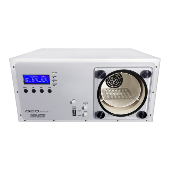
- Page 8 UNIT DIAGRAM & PARTS LISTING Below you will find a diagram of the Model 2000 SP’s various operational parts. FRONT Status Indicator Comm Indicator Local Indicator Fault Indicator LCD Display Fill Port Desiccant Sample IN “NEXT” Button Probe Port “UP”...
-
Page 9: Supplies Needed
QUICK START - FILLING RESERVOIR Supplies Needed Fill Syringe Distilled Water Locate the Fill Port The port is labeled and located on the middle lower portion of the front panel. Remove the Fill Cap Rotate Counter-Clockwise to remove. Attach Fill Syringe to Fill Port Press the fill syringe tip into the fill port, then rotate the cap clockwise to secure. - Page 10 QUICK START - FILLING RESERVOIR Elevate and Fill Syringe - Pour distilled water into the elevated tube body. - Take care not to insert any air into the reservoir. - Monitor the water level indicator while filling. Loosen and Remove Syringe Turn the fill syringe tip counter-clockwise to loosen.
- Page 11 QUICK START - POWERING THE UNIT Supplies Needed Power Supply Cable Locate the Power Input Plug Power Supply into Wall Plug Power Supply into Unit Set Power Switch to “ON”...
-
Page 12: Boot Screen
QUICK START - UNIT OPERATION Boot Screen Our Company Name Model Number Serial Number Firmware Version Number... -
Page 13: Observe The Display
The ‘EXIT’ button has one additional use when the Model 2000 SP is first started it may not have sufficient water vapor to allow the setting of higher relative humidity values. In this case the front panel will flash the word ‘WARMING’. - Page 14 The ‘STATUS’ light indicates the unit is active. The ‘COMM’ light indicates the unit is receiving commands from the GEO Model 2000 SP Windows application. The ‘LOCAL’ light indicates that the unit’s environmental condition is being modified locally from the front panel. That is the current chamber environment has overridden the setting made by the GEO-DFB application.
-
Page 15: Remove The Door
QUICK START - CHANGING DOOR Unscrew the Corner Screws Remove screws by turning in a counter-clockwise motion. Loosen Center Screw In some door variations, there is a center screw that serves the purpose of creating a tighter seal. If this screw exists, it must also be loosened using a counter-clockwise motion before the door can be removed. -
Page 16: Unit Configuration
Control / Reference Probe Configuration The probe calibration screen allows the user to introduce a calibration offset to the internal probe used to control the GEO Calibration 2000 SP chamber. This allows the user to calibrate the internal probe to an external reference. -
Page 17: Error Codes
ERROR CODES The Model 2000 SP displays error codes through the secondary display. These are intended to communicate machine status to the user. Codes and Descriptions Error Code Description “No Analog Detected” Internal Hardware Fault Detected “Internal Probe Fail” Internal Hardware Fault Detected Temperature probe fault. -
Page 18: Specifications
ENCLOSURE Material Insulated Plastic CAPACITY 6 RH Probes 6 - 25 mm PROBE PORTS 6 Ports Model 2000 SP | ENTIRE ASSEMBLY POWER SUPPLY Universal 100 - 260 VAC - 50/60 Hz WATER Reservoir 150 mL Spill Resistant Water Quality... - Page 19 2000 SP door and replace the adapter if necessary. Ensure the door is securely fastened to the chamber. Insert UUT Insert your UUT at least 3 inches into the Model 2000 SP chamber. Program Unit Set-points Allow the unit to reach the programmed set-points and settle.
- Page 20 Control Probe / Reference Sensor Overview The Model 2000 SP functions through the use of a dual PID controller. This controller takes the humidity and temperature values from an internal capacitance probe and further performs cal- culations that are then used to generate the user entered humidity and temperature set points.
- Page 21 REFERENCE RECALIBRATION Self Recalibration Procedure To read the recalibration procedure of the control / reference probe, please refer to the unit’s user manual, and the HW4 software manual found at the following URLs: https://s.campbellsci.com/documents/ca/manuals/hc2-s3-l_man.pdf https://goo.gl/n7qE1G https://www.instrumart.com/assets/rotronic-hygroclip2-probes-manual.pdf Before recalibration of any control probe, ensure that the unit and probe have both completely settled at 23ºC for at least ten minutes.
- Page 22 USB Port Unit Offset Calibration via Hyper-terminal The Model 2000 SP also allows users to make two, single point adjustments for both tempera- ture and humidity. It is recommended that users recalibrate their unit as needed to fit their overall uncertainty requirements.
- Page 23 ENTERING MODEL 2000 SP OFFSETS Reading the COM Port At this time, plug the unit’s power supply into an approved power source. Plug the USB mouse and keyboard into the Unit. Toggle both the power switches to the “ON” position.
- Page 24 ENTERING MODEL 2000 SP OFFSETS Connecting Through PuTTY In PuTTY, select Session menu under Category on the left Input your COM Port (reference Reading the Serial Port instruction from above) into the Seri- al line field Under Connection type, select Serial...
- Page 25 ENTERING MODEL 2000 SP OFFSETS Changing Humidity and Temperature Offsets PLEASE NOTE: #.# is a placeholder In the following instructions, replace # with your desired integers. (For example, #.# would become 1.2 or -0.2) Temperature: type TOFFSET #.# and press the Enter key. The unit will query and display the temperature offset.
-
Page 26: Safety Warning
Make sure the ground conductor in the power cord is connected to a functioning ground. ● Disruption of the ground could put voltage on the chassis that could cause death. Use the Model 2000 SP only as specified, or the protection supplied by the Product can be ● compromised. - Page 27 SAFETY WARNING Disposal Safety Information European Union—Disposal Information The symbol above means that according to local laws and regulations your product and/or its desiccant shall be disposed of separately from household waste. When this product reaches its end of life, take it to a collection point designated by local authorities. The separate collection and recycling of your product and/or its desiccant at the time of disposal will help conserve natural resources and ensure that it is recycled in a manner that protects human health and the environment.
-
Page 28: Technical Support
Fax: +00/(1) 631 / 471 - 6158 support@geocalibration.com www.geocalibration.com GEO Calibration Inc 2190 Smithtown Avenue, Ronkonkoma, NY 11779, USA Tel.: +001 (631) 471 - 6157 ● Fax: +001 (631) 471 - 6158 support@geocalibration.com ● www.geocalibration.com © GEO Calibration Inc. 2017... - Page 29 REPAIRS Unit Repair Procedure Contact GEO Calibration and request an RMA #. ● Have the Product information ready such as the purchase date and serial ● number to schedule the repair. Ship the unit to GEO in the original shipping container or one designed ●...
-
Page 30: Unit Maintenance
UNIT MAINTENANCE Maintenance Schedule GEO Recommendation ● GEO Calibration recommends that the unit be annually shipped back to our facility for general maintenance. Daily Semi-Annual As Needed General Cleaning Refill Reservoir with Distilled (Use Proper Cleaning Control Probe Calibration Water... - Page 31 Desiccant Overview The Model 2000 SP ships with a fresh desiccant canister. Each time the Model 2000 SP dries the internal volume of air, the desiccant will become more saturated with water. For optimal perfor- mance, the user must periodically replenish or replace the used desiccant. The desiccant type is molecular sieve, which may be regenerated by the user through heating.
- Page 32 MAINTENANCE GUIDE - DESICCANT CHANGE Changing the Desiccant Instructions Power Off the Unit Ensure that the unit is powered off before proceeding with a desiccant change. Loosen Hook & Loop Straps Firmly Grasp Desiccant This will cause the old desiccant canister to slide from the female adapters.
- Page 33 MAINTENANCE GUIDE - DESICCANT CHANGE Changing the Desiccant - Continued Firmly Insert Desiccant Canister Ensure the hose barbs properly line up with the sockets on the inside of the desiccant housing. Press with Force to Ensure Firmly press the seal with both thumbs into the canister housing.
- Page 34 MAINTENANCE GUIDE - DESICCANT REFILL Desiccant Refill Instructions Remove Desiccant Follow the initial steps from the previous section entitled “Desiccant Change”. Open Top Cover of Desiccant Save the spring, the sieve and the three white felt filters. Discard previous desiccant. Wipe the inside of the desiccant cannister with a clean cloth.
- Page 35 MAINTENANCE GUIDE - DRAINING THE UNIT Draining the Unit Locate the Main Drain Port Turn the cap counter-clockwise to remove. Move the Unit to Table Edge Position a bowl shaped object underneath the unit to catch the drained water. Remove the Drain Cap Tilt the unit to ensure maximum water removal.
- Page 36 MAINTENANCE GUIDE - PROBE REPLACEMENT Locate Probe Connector Press Probe into Connector Slowly rotate the probe head as you press into the cabling body. You will feel the probe “seat” itself once the male - female parts align. Secure Metal Connector Twist the metal connector away from the chamber entrance to secure the probe head to the probe cabling body.
- Page 37 MAINTENANCE GUIDE - PROBE REMOVAL Open Chamber Door Turn the screws counter-clockwise to loosen. Remove the door. Remove Chamber Insert Loosen Metal Connector Twist towards the chamber opening to loosen. Remove Probe Head...
- Page 38 MAINTENANCE GUIDE - CONDENSATION Condensation in the Chamber Power Off the Unit Ensure that the unit is powered off. This is so that no desiccant is wasted while the unit is not in operation. Open the Chamber Door Follow the door opening procedure from the quick start guide.
- Page 39 BIOMEDICAL R&D FACILITIES AGRICULTURAL Headquarters AUTOMOTIVE MANUFACTURING AEROSPACE HOSPITAL / MEDICAL CLEAN ROOMS Proudly Made in the USA CONTACT US: Sales@GeoCalibration.com 2190 Smithtown Ave, www.GeoCalibration.com Ronkonkoma NY 11779 (631) 471 - 6157 © 2017 GEO Calibration Inc. All rights reserved.
Need help?
Do you have a question about the 2000 SP and is the answer not in the manual?
Questions and answers