Table of Contents
Advertisement
Western Products, PO Box 245038, Milwaukee, WI 53224-9538 • www.westernplows.com
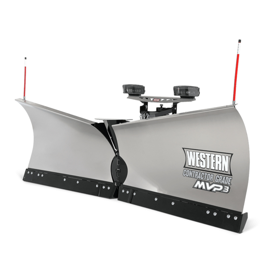
MVP 3™ Snowplow
74475, 74485, 74495, 74585, 74595, 74675, 74685, 74695
74300, 74310, 74400, 74300-1, 74310-1, 74400-1
Read this document before installing the
snowplow.
See your WESTERN
vehicle application recommendations before
installation. The Quick Match selection system
has specific vehicle and snowplow requirements.
Installation Instructions
CAUTION
CAUTION
outlet/website for specific
®
A DIVISION OF DOUGLAS DYNAMICS, LLC
December 15, 2016
Lit. No. 43071, Rev. 05
Advertisement
Table of Contents

Summary of Contents for Western MVP 3 series
- Page 1 Western Products, PO Box 245038, Milwaukee, WI 53224-9538 • www.westernplows.com December 15, 2016 Lit. No. 43071, Rev. 05 MVP 3™ Snowplow 74475, 74485, 74495, 74585, 74595, 74675, 74685, 74695 74300, 74310, 74400, 74300-1, 74310-1, 74400-1 Installation Instructions CAUTION Read this document before installing the snowplow.
-
Page 2: Safety Definitions
SAFETY SAFETY DEFINITIONS WARNING/CAUTION AND INSTRUCTION LABELS WARNING Become familiar with and inform users about the Indicates a potentially hazardous situation warning/caution and instruction labels on the back of that, if not avoided, could result in death or the blade. serious personal injury. -
Page 3: Safety Precautions
WARNING FUSES The driver shall keep bystanders clear of The WESTERN electrical and hydraulic systems ® the blade when it is being raised, lowered or contain several blade-style automotive fuses. If angled. Do not stand between the vehicle and a problem should occur and fuse replacement is the blade or within 8 feet of a moving blade. - Page 4 SAFETY FIRE AND EXPLOSION NOISE Airborne noise emission during use is below 70 dB(A) WARNING for the snowplow operator. Gasoline is highly flammable and gasoline vapor is explosive. Never smoke while VIBRATION working on vehicle. Keep all open flames away from gasoline tank and lines. Wipe up Operating snowplow vibration does not exceed any spilled gasoline immediately.
-
Page 5: Installation Instructions
INSTALLATION INSTRUCTIONS LIFT FRAME TO T-FRAME ASSEMBLY 1. Measure the distance "d" from the ground to the top edge of the receiver bracket. Measure both sides and determine average value for "d." 1. Set aside the blade guides and parts bags. The vehicle electrical harnesses and Owner's Manual Top edge of packet are in the bag with the headlamp box. - Page 6 INSTALLATION INSTRUCTIONS Pivot Bar to Pivot Plates STAND SHOE 1. Position the T-frame and pivot bar between the WARNING pivot plates, aligning the hole at each end of the The stand plunger spring is shipped pivot bar with the appropriate hole in the pivot compressed and tied.
- Page 7 INSTALLATION INSTRUCTIONS T-FRAME TO BLADE ASSEMBLY 4. Move the snowplow into a normal operating position. 1. Remove the blade wings from the crate. Remove 5. Remove the protective packaging from the angle the four shipping straps, then replace the cutting rams.
- Page 8 INSTALLATION INSTRUCTIONS 8. Install the center snow deflector using two 9. Install the blade guides with 5/16" x 1" cap screws 3/8" x 1-1/4" cap screws and 3/8" locknuts. and 5/16" locknuts, as shown. Blade Guide 5/16" Locknut 3/8" x 1-1/4" Cap Screw 3/8"...
- Page 9 INSTALLATION INSTRUCTIONS HEADLAMPS Cable Tie Anchors WARNING Your vehicle must be equipped with snowplow headlamps and directional lights. Cable Ties Headlamps, hardware and instructions are found in Headlamp the headlamp box. Additional hardware (two 1/2" flat Channel washers) can be found in the parts bag. Battery Cable 1.
-
Page 10: Hydraulic Unit
With the snowplow wings and lift ram fully retracted, the fluid level should reach the fill hole. If additional fluid is needed, fill the reservoir with Fill Plug WESTERN High Performance Hydraulic Fluid ® to –40°F (–40°C), or other fluid conforming to... -
Page 11: Blade Drop Speed Adjustment
OPERATIONAL TEST AND FINAL ADJUSTMENTS BLADE DROP SPEED ADJUSTMENT LEVEL T-FRAME 1. With snowplow attached to the properly ballasted WARNING vehicle and blade lowered to ground, the T-frame Keep 8' clear of the blade when it is being should be parallel with the ground. If not, place the raised, lowered or angled. - Page 12 OPERATIONAL TEST AND FINAL ADJUSTMENTS STACKING STOPS Short Configuration Refer to the specifications table below to determine Tall whether the snowplow installation requires stacking Configuration stops to be added on the T-frame. If stacking stops are required: 1. Ensure that both stacking stops are installed in either the short or tall configuration, as determined by the specifications table.
- Page 13 OPERATIONAL TEST AND FINAL ADJUSTMENTS CENTER CUTTING EDGES Lubricating the Pivot Pin Hinge The center cutting edge spacer plate is located on the Using a rubber-tipped seal-off coupler tip, apply a T-frame below the pivot pin hinges. good quality multipurpose grease at the five grease points along the center pivot pin hinge.
- Page 14 OPERATIONAL TEST AND FINAL ADJUSTMENTS FINAL INSPECTION AND ADJUSTMENT snowplow on the ground and the lift ram fully collapsed, attach the chains to the lift arm hooks in the tightest possible link. This adjustment will WARNING provide for optimum transport height, blade float, Keep 8' clear of the blade when it is being and stacking stop clearance.
- Page 15 OPERATIONAL TEST AND FINAL ADJUSTMENTS VEHICLE LIGHTING CHECK With headlamp switch OFF, activate the vehicle DRLs. 1. Verify the operation of all vehicle front lighting Snowplow lighting harness DISCONNECTED: prior to connecting the snowplow harness. • Vehicle DRLs should be ON. •...
- Page 16 Western Products or the vehicle manufacturer may require or recommend optional equipment for snow removal. Do not exceed vehicle ratings with a snowplow. Western Products offers a limited warranty for all snowplows and accessories.
Need help?
Do you have a question about the MVP 3 series and is the answer not in the manual?
Questions and answers