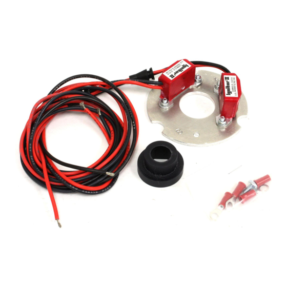
PerTronix Ignitor II Instructions
Electronic ignition bundle
Hide thumbs
Also See for Ignitor II:
- User manual ,
- Installation instructions (2 pages) ,
- Instructions (2 pages)
Advertisement
12-VOLT NEGATIVE GROUND INSTRUCTIONS
FOR PART NUMBERS:
91541
91542
91543
91545
91548
91549
91561
91562
91568
91585A
92541
91567A
12-VOLT NEGATIVE GROUND INSTRUCTIONS
PRESTOLITE DISTRIBUTORS
GENERAL INFORMATION
1. IMPORTANT: Read all instructions before starting installation.
2. DO NOT USE WITH SOLID CORE SPARK PLUG WIRES.
3. The Ignitor II ignition can be used in conjunction with most ignition coils rated at
0.45 ohms or greater.
4. All external resistors must be removed to achieve optimum performance from the
Ignitor II ignition system.
5. The Ignitor II is compatible as a trigger for most electronic boxes.
PRIOR TO INSTALLATION TURN IGNITION SWITCH OFF OR
DISCONNECT THE BATTERY.
1.
Some magnet sleeves have green or blue tape, DO NOT REMOVE IT.
2.
91541, 91542, 91561, and 91562 Ignitor kits only: Two types of rotors
are used in Prestolite distributors. These are shown below. The Ignitor
only works with the type of rotor shown on figure "A". If the rotor is of
the type shown in figure in figure "B" a new cap and rotor will have to be
purchased.
Ignitor #
91541, 91542
Cap
Rotor
Prestolite
3-129
4-93
Borg Warner
C207
D181
Echlin (Napa)
AL165
AL150
Standard (SMP)
AL149
AL168
3.
Remove distributor cap and rotor from distributor. Do not disconnect spark
plug wires from cap. Examine cap and rotor for wear or damage. Replace
as needed.
4.
Remove the point wire from the coil negative terminal.
5.
Remove the screws retaining the breaker plate and remove the complete
breaker plate assembly from the distributor housing.
91561, 91562
Cap
Rotor
3-127
4-93
C205
D181
AL155
AL150
AL480
AL168
Advertisement
Table of Contents

Related Manuals for PerTronix Ignitor II


Summary of Contents for PerTronix Ignitor II
- Page 1 2. DO NOT USE WITH SOLID CORE SPARK PLUG WIRES. 92541 91567A 3. The Ignitor II ignition can be used in conjunction with most ignition coils rated at 0.45 ohms or greater. 4. All external resistors must be removed to achieve optimum performance from the Ignitor II ignition system.
- Page 2 Line up hole or cutout on the Ignitor plate to the wire exit hole in the distributor housing. • 91548 kit only: Line up “X” mark on the Ignitor II plate to the wire exit hole on distributor housing. •...
Need help?
Do you have a question about the Ignitor II and is the answer not in the manual?
Questions and answers