Advertisement
Advertisement
Table of Contents

Summary of Contents for Solartron DR600
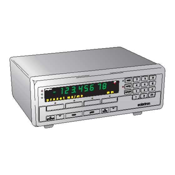
- Page 1 Digital Readout Model No. DR600 & DR700 installation manual...
- Page 2 1.0 Index Section Title Page Index ..... . . Safety Summary ....Service &...
-
Page 3: Safety Summary
2.0: Safety Summary This Equipment is designed as Safety Class I CAUTION statements identify conditions or apparatus to comply with EN61010-1. practices that could result in damage to the equipment or other property. Service Safety This equipment has been designed and tested to Symbols in this Manual meet the requirements of the Low Voltage Directive This symbol indicates where applicable... - Page 4 2.0: Safety Summary (continued) WARNING: Do not operate in an explosive CAUTION: Use correct Fuse atmosphere To avoid a fire hazard, use the correct fuse type, voltage and current rating as WARNING: Do not remove covers or panels specified for the equipment. Refer fuse To avoid personal injury, do not remove covers replacement to qualified service personnel.
-
Page 5: Service And Repair
At the rear right of the Digital Readout parts other than the fuse. remove the fuse cover of the IEC320 This equipment must be returned to your Solartron connector and replace the fuse with the dealer for all other service and repair. -
Page 6: Measurement Configurations
- connection of up to 30 probes the Digital Readout a supplementary power supply (Linear Encoders and/or interface module will be required Digital Probes) and allocated (Solartron Part No. 911173). to a single program. 3.0: Handling & Maintenance Part No. 502001 Issue 6... -
Page 7: Digital Readout Interface
5.0: Digital Readout Interface 5.1 Connecting 1 or 2 Probes Probe(s) must be identified to the Digital Readout when first installed. Simply press probe tip when To connect a Linear Encoder or Digital Probe prompted. ensure cable from Probe Interface Electronics (PIE) is at bottom of unit and plug into either left hand or right hand side of recessed receptacle. - Page 8 5.0: Digital Readout Interface (continued) 5.2: Connecting up to 30 probes Mixed probe capability 9-way cable solartron solartron Plug cable into either lefthand or righthand side of recessed receptacle in rear panel Installation using T-CON ORBIT Network program enter setup .
-
Page 9: Orbit Network Connections
6.0: Probe Interface/Orbit Network Connections Connector type: 9 way D-sub female Function RS485(A) RS485(B) View from rear of unit 6.0: Probe Interface/Orbit Part No. 502001 Issue 6 Network Connections... -
Page 10: Rs232
7.0: RS232 7.2: Voltage Levels (Allows measurement readings to be sent to printer or PC) TXD and RXD voltage levels logic level (active) -3V to -15V Connector type 25 way D-sub female logic level (not active) +3V to +15V RTS, CTS, DSR and DTR voltage levels logic level (active) +3V to +15V logic level (not active) - Page 11 7.0: RS232 (continued) Connection between Digital Readout & printer or PC using RTS/CTS and DTR/DSR 9 10 Text Reading 7.4: Baud Rate 300, 600, 1200, 2400, 4800, 9600, 19200, 28800, 57600 Message terminated by [carriage return] [line feed] 7.5: Data Format 1 start bit Key: 7 data bits Text:...
- Page 12 7.0: RS232 (continued) PC or printer to Digital Readout Command Character Description <Send Requests displayed Measurement> measurement to be sent <X ON> Stop transmission of message <X OFF> Restart transmission of message • Freeze display The numeric display reading can be programmed to 'freeze' when RS232 option is selected in ext menu.
-
Page 13: Input/Output Connections
8.0: Input/Output Connections Allows remote switches or inputs to be used in Pin Assignment place of Digital Readout keys and displayed value Remote ZERO to be frozen. Range Lamp status can be used to Remote LOAD control external relays. Remote PRINT •... - Page 14 8.0: Input/Output Connections (continued) • Remote ZERO: Performs same function • Remote Freeze aspressing zero key when input is taken low The Digital Readout can be programmed then high. to freeze the displayed reading as follows: • Remote LOAD: Performs same function as •...
- Page 15 8.0: Input/Output Connections (continued) • Remote Program Up/Down performs the • Active low, edge triggered. same function as pressing the program • Only one input to be active at a time. program keys when input is taken low •...
- Page 16 8.0: Input/Output Connections (continued) • Misc. • Output schematic Pin Function Unused Unused Unused Unused Unused Outputs • Open Collector, active low • Range lamps within tolerance/low/high operate on actual limit set values with no hysteresis • Delay until signal output: ≤...
-
Page 17: Motor Drive Connections
9.0: Motor Drive Connections Provides dc power for probe motor drive. • When motor key or remote Motor selected then Pin Function Motor + = 0V Motor - = +12V Motor + Motor - • When motor key or remote Motor ... -
Page 18: General Specification
10.0: General Specification ENVIRONMENTAL Power 15W max Operating Temperature (°C) 0 to 40 deg. C Line fuse 2A T Storage Temperature (°C) -20 to 60 deg. C Fuse size 20mm Humidity 0 to 95% non condensing Safety Rating EN61010-1 Nominal Dimensions Width 235mm IP Rating...
Need help?
Do you have a question about the DR600 and is the answer not in the manual?
Questions and answers