Advertisement
Quick Links
Advertisement

Summary of Contents for Trinabess PowerCube 2.0 DC
- Page 1 PowerCube 2.0 DC Installation Guide – Australia & New Zealand Feb 2018 V1.5...
- Page 2 Contents • 1. System Introduction • 2. Unpacking the products • 3. System Installation Steps • 4. WIFI Monitoring Setup Guide...
- Page 3 System Introduction • System Topology • Power Box DC • PowerCube 2.0...
- Page 4 PowerCube System Topology Power Box (DC – “Hybrid Inverter”): • DC/AC bi-directional Power Conversion Equipment (PCE) • Mainly applied and developed for the renewable energy generation system • The interface between the grid, solar PV and the battery storage • Designed for lithium-ion batteries PowerCube –...
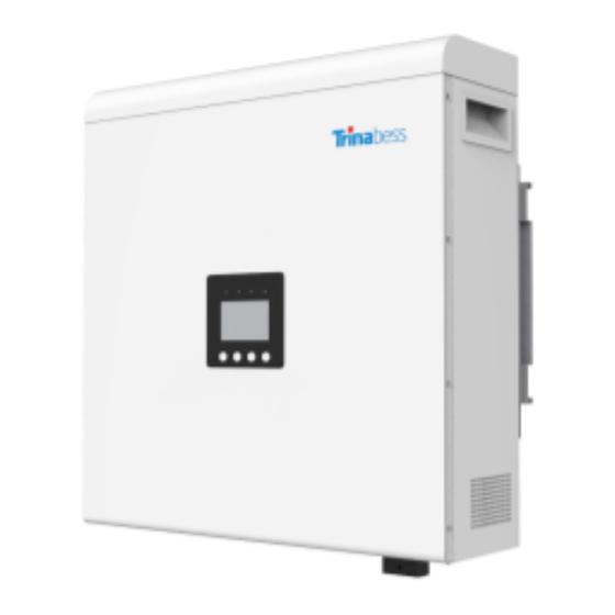
- Page 5 Power Box (DC – Bess Hybrid Inverter) 610mm Length 515mm Width 192mm Height Weight 30kg...
- Page 6 PowerCube (Battery Storage) Advantages: • The PowerCube and accessories are designed for simplicity and convenience • Can be completed by one person • Integrated Isolator design reduce the cost and time required for installation PowerCube 2.0 Casing: Battery Pack: • Outdoor rating –...
- Page 7 Upacking the products • Battery Packs • PowerCube 2.0 Casing • Power Box...
- Page 8 Battery Packs...
- Page 9 PowerCube Component Part Name Quantity Casing Battery Pack Power Cable with connectors connecting between battery packs RJ45 communication line with connectors Connectors without Power Cable RJ45 communication 2 (1*backup) connectors Wall plug M8 bolt M8 Anti-Theft bolt...
- Page 10 Power Box DC Aviation Plug Aviation Plug (Male) (Female) Solar PV connect (2 pairs) Plug & Screw Fixings Anderson plug & connector (Batt) Communication Cable & Adapter...
- Page 11 System Installation Steps • Installation tools and accessories • Single Line Diagram • Powerbox installation • Powercube installation • BESS installation • System Initialization • System Setting...
- Page 12 Installation Tools Hammer Drill Recommend drill dia. 8 & 10mm...
- Page 13 Installation Accessories Depending on the site-specific situation and local electrical compliance requirements, some if not all of the following parts will be required: • AC circuit breakers – Minimum four 32A circuit breaker is required next to the BESS system and inside the main switchboard.
- Page 14 System Connection – Single Line Diagram TB5200SH internal wiring diagram...
- Page 15 Installing the hybrid inverter Choose a proper position for the mounting bracket ≥300mm on the wall and mark it Φ10 drill template to drill holes on marked position Fix the expansion bolt into the hole ≥200mm Fix wall bracket on the wall Fix screw through bracket to expansion tube, adjust ≥200mm the bracket position and screw in...
- Page 16 Powercube installation – PowerCube Mounting Step 1: Remove the enclosure cover ≥300mm Step 2: Remove the Circuit Breaker cover Step 3: Use the cardboard template provided to do wall-mount hole “marking” and drill holes accordingly Step 4: Insert wall plug and drive the M8 bolts Note: Place two anti-theft bolts in the middle hole...
- Page 17 Powercube installation – Battery packs Once the Powercube enclosure have been secured with bolts. Step 1: Insert the packs into the mounted casing Step 2: Turn the baffle secure the battery packs...
- Page 18 Powercube installation – BESS connections Connecting the packs together Step 1: Connect a master pack. The master should have the breaker Negative cable connected to it. It should also have the label “Master Mode” Step 2: Connect rest of the negative cables Master Step 3: Connect the positive cables.
- Page 19 System connection – Powercube Battery pack overview Connection Points (CP) CP 1 Cathode (-) CP 6 Link Port 1 CP 2 Cathode (-) CP 7 CP 3 Anode (+) CP 8 RS485 CP 4 Anode (+) CP 9 POWER(ON/OFF) CP 5 Link Port 0 CP 10 Soft Starter...
- Page 20 System connection - Battery Modules (2 Packs) Connection - Wire DC isolator (supplied) Powerbox (DC) DC Negative cable DC Positive cable Master Comms Relay Link 1 Plate (supplied) Link 0 Energy Meter Powercube battery packs...
- Page 21 System connection - Battery Modules (3 Packs) Connection - Wire Comms DC isolator Relay (supplied) Plate (supplied) Powerbox (DC) Energy Meter Master Link 0 Link 0 Link 1 Link 1 Powercube battery packs...
- Page 22 System connection - Battery Modules (4 Packs) Connection - Wire Master Energy Meter...
- Page 23 BESS installation – BESS connections Position the BESS distribution box (recommend 4 pole) ≥100mm ≥200mm Breaker Negative cable Breaker Positive cable Inverter comms cable...
- Page 24 BESS installation – BESS connections Position the BESS distribution box (recommend 4 pole) 1. Prepare and run the comms cables, AC cables conduit (if applicable) to the DB. 2. Prepare and run the DC cables and conduit to the inverter. Inverter to Battery comms cable Battery to Inverter comms cable...
- Page 25 BESS installation – Hybrid inverter Connections Connecting the inverter cables 1. Prepare the AC Grid Critical load connectors. 2. Connect the AC connectors to the inverter. 3. Connect the Anderson plug to the DC cables 4. Connect the comms cable RS485 port 5.
- Page 26 BESS installation – BESS connections Connecting the comms cables (cables already labelled) Step 1: Insert the relay board on to the DIN rail. Step 2: Connect inverter comms cable to relay board Step 3: Insert the powercube comms cable positive to 3, negative Step 4: Run the energy meter comms...
- Page 27 BESS installation – BESS connections Step 2: Connect to the critical load Connecting the AC cables Actives: A) Wire the Critical load AC breaker Step 1: Connect to the grid: B) Wire to the critical load Actives: Neutrals: A) Wire straight to critical load A) Wire the Grid AC breaker Earth: B) Wire to the Energy Meter...
- Page 28 BESS installation – Main Switchboard connections Critical Load Energy Meter Utility Meter To Energy Meter Connecting Wires from BESS DB Step 1: Connect the Critical Loads circuits Step 2: Connect energy meter circuits (an AC Circuit Breaker may be needed for local wiring requirements) Step 3: Connect energy meter to main...
- Page 29 BESS installation – Complete Note: Sample Installation for reference...
- Page 30 System Initialization – Changing settings Note: Please double check the connections (notably AC & before operation. Power on the BESS system per the following steps: 1. Turn ON PV array isolators/circuit breakers (if applicable) 2. Turn ON AC circuit breaker between Power Box Grid port &...
- Page 31 System Initialization - System menu keys Item Symbol Meaning Illustration ① Cancel Move back to the upper item or close Move back to the upper item or previous ② ▲ page ③ ▼ Down Move forward to next item or next page ④...
- Page 32 Operation mode adjusted Back up reserved Slave mode Meter address(001-255) Current transformer(01-99)(default 01) Trinabess Communication mode: RS485 Discharging stop capacity (default 20%) Grid feed-in power (0-100%) (default 100%) Restore to the default factory setting(RST1111) Note: the LCD background light will be turned off if no actions within 2 minutes.
- Page 33 System Setting – Changing the time for the first time Time Setting: Usually during the first initialization, the time need to be changed. 1. At the standard interface, long press the “OK” button for 3 seconds to enter the setting menu.
- Page 34 System Setting – Setting Smart Meter address Smart Meter Address Setting: Usually during the first initialization, the smart meter address need to be changed. 1. At the standard interface, long press the “OK” button for 3 seconds to enter the setting menu.
- Page 35 System Setting – CT address Smart Meter Address Setting: Usually during the first initialization, the CT address need to be changed. 1. At the standard interface, long press the “OK” button for 3 seconds to enter the setting menu. password “1111” 2.
- Page 36 System Setting – Zero Export function (optional) Smart Meter Address Setting: The Zero export function can be utilized in some regions by changing in the “FED” settings. 1.At the standard interface, long press the “OK” button for 3 seconds to enter the setting menu.
- Page 37 System Initialization – Start-up Note: Please double check the connections (notably AC & DC) before operation. Power on the BESS system per the following steps: 1. After changing all the setting. Restart the system by turning off all AC & DC circuit breakers (no particular order) 2.
- Page 38 System Initialization – LCD display menu definition Item list Display contents Voltage Current Current Voltage Voltage Current GRID voltage(on-grid) GRID voltage(on-grid) EMERGENCY LOAD voltage(off-grid) EMERGENCY LOAD current(off-grid) Inverter Temperature Grid frequency Daily PV production Battery capacity software version No. of SolDate5200TLcommunication conversion board CPU software version No.
- Page 39 WIFI Monitoring Setup Guide • Establish WLAN (Wi-Fi) Connection • APP Setup • BESS System Monitoring...
- Page 40 Establish WLAN (Wi-Fi) Connection - Connecting to inverter Wi-Fi • Connected with the Inverter Wi-Fi SSID which is Open up an internet browser using a computer PC same as inverter serial number or from any smart device. • Enter the inverter IP address in the address bar (URL) to open up its settings and configurations:...
- Page 41 Establish WLAN (Wi-Fi) Connection - Set-up the WLAN connection • “Save & Reboot” Enter and connect to local WiFi network SSID Click and restart, wait at least 2 password minutes. If the device IP address is no longer 0.0.0.0, then the device is connected to the Internet successfully.
- Page 42 Establish WLAN (Wi-Fi) Connection - Set-up the user account • Visit the website portal (http://cloud.trinabess.com) and *Username: free to create (with 5-15 letters click “register” /figures). • Caution: when Username is created, it cannot be changed. • * Email Address: fill in a frequently-used email address.
- Page 43 APP setup - Downloading the APP Search “Trinabess” in app store (IOS) For android, download via this link or QR code: http://cloud.trinabess.com/TrinabestAgent/resources/app /trinabess.apk...
- Page 44 BESS System monitoring - Demo account Webpage: http://cloud.trinabess.com/ Username: pan1 Password: 123456 2.4.1 2.4.3 2.4.5 2.4.2 2.4.4...
Need help?
Do you have a question about the PowerCube 2.0 DC and is the answer not in the manual?
Questions and answers