
Summary of Contents for EES BSM
- Page 1 Panel Mounted Fault Annunciator Series BSM – Panel-mounted fault annunciator (2nd Generation) Operating manual MSM-BSM2G-BA-UK-001...
-
Page 2: Table Of Contents
2.6 Customer service ..........................8 2.7 Copyrights, trademark rights, GNU licenses ..................9 3 Functional description ........................10 3.1 Basic set-up of the BSM ......................... 10 3.2 Internal Relay cards (optional) ......................11 3.3 Dual power supply (optional) ......................11 3.4 Cascading of several fault annunciators .................. - Page 3 Table of content 7 Parameterisation by Excel-file ......................41 7.1 Alarm channels and IEC objects ..................... 42 7.1.1 Alarms ............................42 7.1.2 IEC-objects of the reporting channels ..................43 7.2 Repeat relays and IEC objects ...................... 44 7.2.1 Relays ............................44 7.2.2 IEC-objects of the repeat relays ....................
-
Page 4: Validity
Validity 1 Validity The description covers BSM devices with the following options: Number of reporting inputs 8 Reporting inputs 16 Reporting inputs * 24 Reporting inputs 32 Reporting inputs 40 Reporting inputs 48 Reporting inputs Operating voltage 24 V AC/DC... - Page 5 * Also available in wide housing (96 x 192 mm) ** 16 way fault annunciator with integrated repeat relays only available in wide housing (96 x 192 mm) Table 1.2: Matrix of BSM-P variants Version of the described parameterisation software: EES BSM Parameterisation V3.0.4. MSM-USM2G-BA-UK-001 Page 5 of 45...
-
Page 6: General Notes
This manual provides the safe and efficient use with the devices of the fault annunciating series BSM (in the following called “BSM”, “fault annunciator” or “device”). The manual is part of the device and must be stored always accessible for the personnel in direct proximity of the device. - Page 7 General notes DANGER! This combination of symbol and signal word warns of a hazardous situation which can lead to death or severe injuries if not avoided. WARNING! This combination of symbol and signal word warns of a possibly hazardous situation which can lead to death or severe injuries if not avoided.
-
Page 8: Safety Instructions
Telephone + 49 (0) 7191/182-0 Telefax +49 (0) 7191/182-200 E-Mail info@ees-online.de Internet www.ees-online.de Further we are looking forward to receiving feedback and experiences which result from the application and are useful for improvement of our products. Page 8 of 45... -
Page 9: Copyrights, Trademark Rights, Gnu Licenses
The surrender of this manual to third parties, reproduction in every type or form including extraction of contents are not tolerable without written permission from Elektra Elektronik GmbH & Co. Störcontroller KG (in the following “manufacturer” or “EES”), except for internal purposes. Any violations oblige for compensation. The manufacturer reserves the right for additional titles. -
Page 10: Functional Description
All annunciators of the series BSM feature status retention upon power failure. This means that after restoration of the supply voltage, the alarm status as of the moment of power failure is retained. -
Page 11: Internal Relay Cards (Optional)
The communication within the annunciating system is done through the integrated CAN-Bus interface. The devices are connected to each other by means of a patch-cable. The first BSM or USM works as “master” and the connected BSM-C or BSM-P act as “slave”. Thus a system with up to 192 (4*48) signals can be realized. -
Page 12: Labelling
The designation strips with signal names can be created and printed directly from the parameterisation software for the BSM-P. For manual generation of labelling strips for BSM-C or BSM-P patterns in Word-format are available. Fig. 3.3: Insertion of labelling strips after removing... -
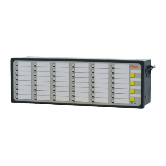
Page 13: Monitoring Leds, Buttons And Connections
In this section, the BSM-P with 8 alarm channels and integrated repeat relays is used to illustrate the general setup of a BSM. The number of signal inputs and the colours of the alarm LEDs can deviate depending on the configuration and size of the respective BSM. -
Page 14: Diagnosis
Functional description 3.7 Diagnosis For monitoring and evaluation of the system functions diagnosis information is available by signalling of errors on the watchdog LEDs and relay contacts. 3.7.1 Watchdog-LED „Self-monitoring“ and Live-relay The watchdog-LED „self-monitoring“ gives information about the current status of the annunciator device or system: ... -
Page 15: Error Codes
EES for inspection. This error can occur in cascaded systems. It will be issued Communication within when the connection between the master BSM and at least cascaded annunciator system one of the slave BSM is disrupted. Please verify the... -
Page 16: Terminal Assignments
Functional description 3.8 Terminal assignments Fig. 3.5: Terminal assignment BSM Page 16 of 45 MSM-BSM2G-BA-UK-001... -
Page 17: Technical Data
37…73 V DC or 26…51 V AC 48 V AC/DC or 60 V DC 100…370 V DC or 85…264 V AC 110 V AC/DC or 220 V AC/DC Table 3.3: Supply voltage keys – BSM Signal voltage U Threshold for alarm Maximum... - Page 18 92 x 282 approx. 1,00 Table 3.6: Dimensions – BSM * BSM-…-R are variants with integrated repeat relays. ** A 16-way annunciator with integrated repeat relays can only be realised in the variant 16 wide (housing 96 x 192 mm).
- Page 19 Functional description Dielectric strength Electromagnetic compatibility Noise immunity acc. to DIN EN 61000-3-2 / CLASS A DIN EN 61000-3-3 DIN EN 61000-4-2 / 4/8 kV / Criterion A DIN EN 61000-4-3 / Imm. Test Level 3 / Criterion A DIN EN 61000-4-4 / Imm. Test Level 3 / Criterion A DIN EN 61000-4-5 / Imm.
-
Page 20: Mounting And Installation
4. For a cascaded annunciator system, connect slaves according to steps 2 and 3 and connect the cascaded annunciators to each other by means of a patch cable through the CAN-Bus- interfaces (terminals X7 / X8 at the BSM and terminal X7 at the USM). 5. Connect the power supply and activate power supply. -
Page 21: Configuration
ON - Slave Table 5.1: Assignment of DIP-switch combination S1 If the BSM is not part of a cascaded annunciator system, DIP-switches S1/1 – S1/3 are to be set to OFF (default setting). 5.2 Alarm group related DIP-switch combinations (S10 – S20) The DIP-switches 1 and 2 of these DIP-switch combinations always affect the respective alarm group (8 channels) which is assigned to the respective terminals. -
Page 22: Configuration Of The Relay Groups
The relays are triggered input parallel. The relays are not inverted. For the BSM-P these settings can be changed in the parameterisation software. 5.4 Default settings LED-colour - red for fault signalling and green for operation indication ... -
Page 23: Parameterisation
Parameterisation 6 Parameterisation Alternatively to configuration by DIP-switches the BSM-P can be parameterised by software. To parameterise the device the service and diagnosis interface USB-B (terminal X9) of the BSM-P has to be connected to the PC. System requirements ... - Page 24 Here the respective device according to the present hardware of the device to be parameterised can Fig. 6.2 Dialog be selected. For the BSM-P, please also select the device variant „BSM/WAP-P“. This selection can be changed at a later time, if required.
- Page 25 Parameterisation In the menu bar next to the EES logo, the three main menus are located: Language Parameter Configuration as well as the symbol bar consisting of five push buttons: The push buttons have the following functions: ...
-
Page 26: Main Menu Language
Parameterisation 6.1 Main Menu Language The parameterisation interface can be changed between German and English here. 6.2 Main Menu Parameter The main menu is structured into 5 submenus. Fig. 6.5: Opened main menu „Parameter“ Serial interface Selection of the interface for the device parameterisation ... -
Page 27: Menu Serial Interface
PC). 6.2.2 Menu Monitor The page monitor offers diagnostics for the BSM. On this page the LEDs of the annunciator are displayed with their current status (flashing, steady light, off). Fig. 6.7: Monitor – a diagnosis tool If the annunciator is used within a cascaded annunciator system, each of the devices can be displayed in the monitor by click on the respective radio button „Annunciator 0…3“. -
Page 28: Menu Device Administration
„BSM/WAP-P“ for annunciators of the type BSM-P. From a BSM or USM (Master) and up to 3 slaves (BSM-C or BSM-P) a cascaded annunciator system can be formed providing one common alarm processing (Reporting sequence, forming of collective reports and horn triggering). - Page 29 Parameterisation Fig.6.9: Submenu New/adapt After selection of the required annunciator type from the respective drop down menu, the device will automatically be added to the parameterisation. After all required devices have been edited, please confirm the system configuration with the button „Accept all 4 configurations“. The added slave devices now can be found in the menu „Parameter“...
-
Page 30: Submenu Export/Import
Parameterisation 6.2.3.2 Submenu Export/Import On this page the configuration of the fault annunciator(s) can be stored or a parameter file can be loaded. The following options are available: Store complete parameterisation The parameters of the whole annunciator system (incl. optionally connected slave devices in a cascaded system) are packed to one file and saved. -
Page 31: Menu System
6.2.3.2 Submenu Error Mask Fig. 6.12: Submenu Error mask In this menu the handling of device errors of the BSM can be defined. Blinkcode and Description The entries in this field cannot be edited and show the blinkcode and the corresponding error in clear text. -
Page 32: Menu Master-Device / Slave-Device1
Fig. 6.13: Page Reporting channel Devicename A device designation with a maximum length of 40 ASCII characters can be entered here. This designation serves for identification of the device, is transmitted to the BSM when parameterised and stored there. Page 32 of 45... - Page 33 Parameterisation XML name / variant In these fields declarations for name and version of the respective device parameterisation can be entered. This information is stored in the parameterisation file and on the device and will be read and displayed when loading a parameterisation file or when a device is connected. Comm-Port The selected COM-Port for parameterisation of the connected annunciator (...
- Page 34 Defluttering Raising / falling delay Signal input Debouncing (Supression of Reporting sequence Alarm (Alarm response delay) fluttering inputs) Triggering of repeat relays Relay activated Fig. 6.14: Schematic illustration of the alarm processing in the BSM Page 34 of 45 MSM-BSM2G-BA-UK-001...
- Page 35 Parameterisation To use the settings in one line for one or all other lines, line contents can be copied to the desired line(s). By right-click on the marked line a context menu with the following options opens: Copy Paste Paste to all The latter option fills all lines with the respective contents.
-
Page 36: Submenu Reporting Sequence
Parameterisation 6.2.4.2 Submenu Reporting Sequence Fig. 6.15: Page Reporting sequence In this sub-menu the reporting sequence and the horn triggering can be parameterised. To ensure a flexible adaption of the sequence to the requirements, the reporting sequence is composed from different components, which are explained in the following. -
Page 37: Submenu Buttons & Function Inputs
Horn is triggered by subsequent alarms only if no not retriggerable alarms are at issue. Table 6.2: Options reporting group For additional information on the integrated reporting sequences, please refer to the separate document „Alarm sequences of the EES fault annunciators“. Horn Title Options Note... -
Page 38: Submenu Relay (Function Relays)
Parameterisation Function Note Lamp acknowledgement 1, 2, Optical acknowledgement: Acknowledgement of the alarms in the collective report groups 1, 2 or 3 Reset 1, 2, 3 Reset of the alarms in the collective report groups 1, 2 or 3 Horn Acknowledgement audible alarm Lamp test Lamp test... -
Page 39: Submenu Repeat Relays
Parameterisation Function Note Inverted When activated the switching function is negated Collective report 1, 2, 3 Activated by collective report 1,2 or 3 Horn Relay contact for connection and triggering of an external horn Alive Alive-contact of the internal self-monitoring (fixed assigned to relay 4) Function input 1, 2 Relay follows function input Interface... -
Page 40: Submenu Led-Colour Selection
Parameterisation Output parallel If the relay is triggered from a signal input, it can be defined if the relay directly follows the input (input parallel) or if it is activated until the corresponding alarm is acknowledged (stored alarm = output parallel). -
Page 41: Main Menu Configuration
Excel-files (e.g. data point lists). In this case it is useful to transfer this information to a template and import it into the annunciator. EES provides a template that can be filled in and processed with common procedures. With the Excel file the parameters for the alarm channels, repeat relays and IEC objects can be imported into the BSM. -
Page 42: Alarm Channels And Iec Objects
Parameterisation If the Excel-file contains parameters for additional slave-devices (within a cascaded annunciator system), these can only be imported if the respective annunciators have been edified in the parameterisation of the master annunciator before. The Excel-file has to be of the type .xls, other Excel formats cannot be processed by the annunciator. -
Page 43: Iec-Objects Of The Reporting Channels
7.1.2 IEC-objects of the reporting channels Settings that affect the IEC functionality will be ignored upon direct Excel-import to an annunciator of the type BSM-P. For each alarm channel and IEC type an IEC object is generated. All objects are formed identically and have the same parameters. -
Page 44: Repeat Relays And Iec Objects
Parameterisation 7.2 Repeat relays and IEC objects The name of the tab „EES_Relay“ must not be changed, otherwise the tab will not be processed during the import. 7.2.1 Relays Index (idx) The index is a consecutive number which ensures that the original sequence is reproducible when sorting the table according to certain contents. -
Page 45: Iec-Objects Of The Repeat Relays
7.2.2 IEC-objects of the repeat relays Settings that affect the IEC functionality will be ignored upon direct Excel-import to an annunciator of the type BSM-P. For each repeat relay and IEC type an IEC object is generated. All objects are formed identically and have the same parameters.
Need help?
Do you have a question about the BSM and is the answer not in the manual?
Questions and answers