Advertisement
Installation Instructions
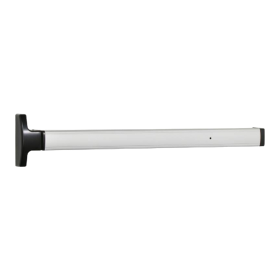
1690 Touchbar
Concealed Vertical Rod
Panic Device
NOTE: The door prep for the 1690 Hex Bottom Rod is different
than for the RL bottom rod. Please verify rod type in package
and prep required (page 16) before prepping the door.
Copyright © 2010 Ingersoll-Rand Company.
All rights reserved.
ININST.1002(G)
ININST.1002
Index:
• Parts List ...................................
• Touchbar Part Numbers ............
• Before Installation .....................
• Installation .................................
• Touchbar Dogging ...................
• Setting Rod Lengths ................
• Re-handing Device ..................
• Field Sizing Device ..................
• 1990 Retrofit Instructions ........
• Template ..................................
2
3
3
4
10
11
11
12
14
16
Advertisement
Table of Contents

Summary of Contents for Ingersoll-Rand FALCON 1690 Touchbar
-
Page 1: Table Of Contents
Installation Instructions ININST.1002 1690 Touchbar Concealed Vertical Rod Panic Device Index: • Parts List ........• Touchbar Part Numbers .... • Before Installation ..... • Installation ......... • Touchbar Dogging ....• Setting Rod Lengths ....• Re-handing Device ....•... -
Page 2: Parts List
PARTS LIST RIM CYLINDER (optional; sold separately) Top Rod Finish Part No. DC13 4270107367 Assembly DC35 4270105986 032210-10 US10 032210-06 US26/28 4270100247 12 13 NOTES 1. See page 3 for touchbar part numbers. Hex Bottom 2. Touchbar shown cut away for visibility. -
Page 3: Touchbar Part Numbers
PARTS LIST (CONTINUED) TOP ROD RL BOTTOM HEX BOTTOM ASSEMBLY ROD ASSEMBLY ROD ASSEMBLY SU latch 4270101806 Jam nut 3/8"-24 4299100004 Bent rod 35.125" long 4270100017 Bent rod 37.812" long (can be shortened by 5") 4270101825 Top rod (can be shortened by 6") quantity 1 piece Jam nut 3/8"-24 4299100004... -
Page 4: Installation
INSTALLATION Install rod assemblies. 1.1. Install top rod assembly into door. Secure with #10-32 x 1/4" housing screws, retaining ring, and rod bearing bushing. Make sure retaining ring fits securely into groove. 1.2. Install bottom rod assembly into door same as top rod assembly. Top rod housing assembly... - Page 5 Prepare hole and wire EL/RX device. (If device is not EL/RX, go to Step 5.) 4.1. Drill 3/8" diameter hole for EL/RX wiring through channel end cap, channel, and inside face of door. 3/8" drilled hole NOTE Hole must be free of burrs. 4.2.
- Page 6 4.3. Wire EL solenoid as shown below. All EL1690 devices are fail secure. PS873 120 VAC power supply Outside control switch EL1690 Electric power transfer Electric (EPT-2 part No. 012011 power EPT-10 part No. 012012) transfer or pivot Potted circuit board CAUTION (part No.
- Page 7 Adjust rods. Top Rod Adjustment 5.1. Dog the device. If it dogs and undogs freely, go to Step 5.2. If it does not, the top rod is too long. To determine how much to shorten the top rod: A. Undog the device. B.
- Page 8 Install outside cylinder. (If no outside cylinder, go to Step 8.) 6.1. Remove traveler lift bracket and axle (Figure 6-1). NOTE 6.2. Cut cylinder tailpiece to correct length (Figure 6-2). The lift arm should remain attached to the device. Removing the axle 6.3.
- Page 9 Install pinion gear support bracket, retainer screw, and axle. 8.1. Install pinion gear retainer, retainer screw, and axle. (Retainer screw and axle are interchangeable.) 8.2. Test NL or HB function. Retainer screw Pinion support bracket Axle Install covers. 9.1. Install center case cover over center case and tighten securely with two (#8 x 5/8" FPHTC) cover screws.
-
Page 10: Touchbar Dogging
TOUCHBAR DOGGING NOTE These instructions are for touchbar dogging of new style DOM 1690 devices. New style devices have two cover screws installed vertically into the center case cover. (Old style devices have four cover screws installed horizontally into the center case cover.) NOTE EL (electric latch retraction) devices cannot be mechanically dogged using the touchbar. -
Page 11: Setting Rod Lengths
SETTING ROD LENGTHS NOTE Factory length settings are for standard 7' door (door height = 83.187") with C dimension = 41.313": TR = 41-7/32" (41.219") and BR = 39-25/32" (39.781") 1. Determine top rod set length TR: TR = door height 0.655"... -
Page 12: Field Sizing Device
FIELD SIZING DEVICE Note: These instructions assume a 1/2" blade stop on the door frame. 1. Determine door clear opening. This is the distance inside the frame. 2. Determine channel cut length A: A = door opening 2-27/32" 3. Verify that A determined in Step 2 is not less than minimum A dimension listed in table. Standard 1690 devices can be shortened by up to 6". - Page 13 8. If hinge stile has not been prepared for channel hinge stile 1/4-20 mounting screws: Place hinge stile end cap into hinge end of channel. Drill through the center of end cap slots using a letter "I" drill. These two holes will be used to transfer location of mounting screw holes to hinge stile when device is applied to door.
-
Page 14: 1990 Retrofit Instructions
1990 RETROFIT INSTRUCTIONS 1. Remove crossbar device, door con studs, traveler, retractor, pinion, pinion bushing, rod bushings and rings from door. Note: Pinion, pinion bushing, and retractor present on NL/HB devices only. Crossbar device Door con studs (4) Hinge stile Lock stile 2. - Page 15 4. Install new rod bushings and retaining rings (refer to Step 1 on page 4 of instructions). 5. Mount the device to the lock stile using the supplied 1/4-20 undercut flat head screws. 6. Position the device horizontally on the door (same distance from bottom of door to bottom of channel on both stiles).
-
Page 16: Template
1-1/4" With Standard 7/8" Cutout on inside Hinge stile Rods and Latches face only 1690 Touchbar 7/16" 1-3/8" Concealed Vertical Rod 1/8" Panic Device 1/4" radius Door Preparation Template 1-3/8" #9 (0.196") drill, c'sink 82° to 25/64" dia., 4 holes, inside face only Lock Hinge...
Need help?
Do you have a question about the FALCON 1690 Touchbar and is the answer not in the manual?
Questions and answers