Advertisement
Quick Links
Manual addendum to RT-21 - September 25, 2018
Overview:
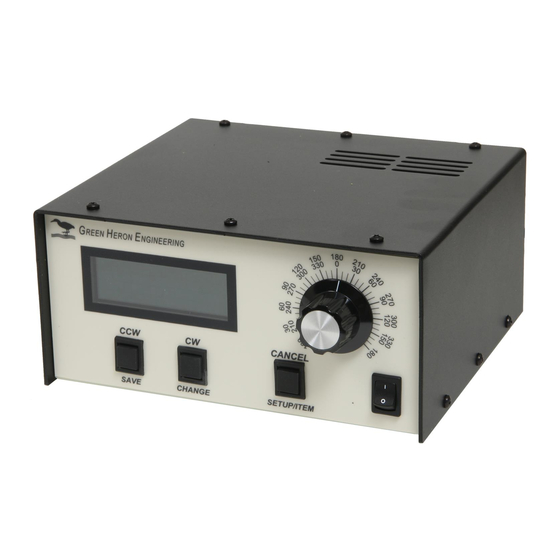
The RT-21 Az-El controller consists of two RT-21 units with a shared power
supply and shared chassis. The unit features a pair of new OLED displays for
sharp, crisp viewing, two main RT-21 PCB each with their own RS232 port, USB
port, and 8 position terminal strip on the rear panel. When teamed with the free
GH Tracker software from the website, this unit provides a fully automatic,
hands-free controller for many different combinations of Az-El rotator schemes.
http://www.greenheronengineering.com/RT_Software.php
The lower board is configured for azimuth and uses the lower display, serial
connectors, and terminal strip. The upper board is configured for elevation and
uses the upper display, serial connectors, and terminal strip.
Compatibility:
The RT-21 Az-El is suitable for:
Yaesu G5400 Az-El units
Yaesu G5500 Az-El units
Alfa Spid Az-El units
M2 Az (OR28900) with MT1000, MT3000 units
Create Design Az and El rotators – (RC5, ERC)
Any combination of Azimuth and Elevation rotators that:
a. Both use AC or Both use DC motors – AND -
b. Both use rotators that are within the capabilities of a standard RT-21
(The RT-21 Az-El is compatible with the Prosistel Az El system as well. Please
contact us for information regarding this rotator.)
Examples of systems that cannot use an RT-21 Az-El. These types of systems
would require separate azimuth and elevation RT-21 controllers:
1. Azimuth using a Prop Pitch motor (with PWM speed control) cannot be
accommodated with the RT-21 Az-El because the Prop Pitch requires the
10 amp motor supply. The RT-21pp must be used for the Prop Pitch
azimuth rotator. (EXCEPTION – we can configure the azimuth side for
relay control without PWM speed control capability, and then utilize an RT-
21 Az-El as long as we match the relay voltage type (ac or dc) with your
choice of elevation rotators.)
2. Azimuth with A Yaesu G2800, and elevation of G550 cannot be
accommodated because the G2800 uses DC motor, while the G550 uses
an AC Motor.
The RT-21 Az-El is compatible with SETUP Utility version 2.1 and later.
RT-21 Az-El Controller
1
Advertisement

Subscribe to Our Youtube Channel
Summary of Contents for Green Heron RT-21
- Page 1 The unit features a pair of new OLED displays for sharp, crisp viewing, two main RT-21 PCB each with their own RS232 port, USB port, and 8 position terminal strip on the rear panel. When teamed with the free GH Tracker software from the website, this unit provides a fully automatic, hands-free controller for many different combinations of Az-El rotator schemes.
- Page 2 Features: RT-21 SETUP UTILITY pc software supports all the RT-21 Az-El is supported in version 2.1 that is available on the website at: http://www.greenheronengineering.com/RT_Software.php The following standard RT-21 features are not included in the RT-21 Az-El Controller: 1. Master/Slave and Counter-rotation features.
- Page 3 4. If your azimuth rotator is a G5400, HAMx or T2X rotator, you will need to add a motor start capacitor across terminals 1 and 2 of the RT-21 azimuth barrier strip. Green Heron will provide you with an appropriate capacitor on request.
- Page 4 5 (Orange) 6 (Blue) (Opt: cable shield to 6-32 ground stud (if shield used) (Shielded rotor cable is not required with an RT-21) CALIBRATION PROCEDURE Existing System from front panel (antenna already installed and working 1. Look at the current direction of the antenna and note the true heading/elevation. Then press SETUP until the displays says “Setup”, then let go and you will be in the “Calibrate”...
- Page 5 Pulse divisor requirement of 720. Some units have other divisors, and the High Resolution versions should be 2880. The RT-21 supports all versions, contact us if you need assistance determining your correct Divider value. 2. The azimuth rotors have no limit switches, so be certain you do not over-travel beyond the limits of your rotor loops!!!! Adjust the antenna position on the mast or turn with the CW or CCW buttons until the antenna is at some physical known heading or elevation.
- Page 6 Create ERC5x Use the RT-21 Manual Appendix A.5 for Connections and Setups for both RC5 and ERC5 rotators. Elevation ERC5 CALIBRATION PROCEDURE 1. Turn the rotor to horizon 0 degrees elevation with the CCW (Down) button watching the antenna, not the display Press the CANCEL and CCW (DOWN) together and hold 2 seconds until the display reads “CAL...
- Page 7 The unit features a pair of new OLED displays for sharp, crisp viewing, two main RT-21 PCB each with their own RS232 port, USB port, and 8 position terminal strip on the rear panel. When teamed with the free GH Tracker software from the website, this unit provides a fully automatic, hands-free controller for many different combinations of Az-El rotator schemes.
- Page 8 Features: RT-21 SETUP UTILITY pc software supports all the RT-21 Az-El is supported in version 2.1 that is available on the website at: http://www.greenheronengineering.com/RT_Software.php The following standard RT-21 features are not included in the RT-21 Az-El Controller: 1. Master/Slave and Counter-rotation features.
- Page 9 4. If your azimuth rotator is a G5400, HAMx or T2X rotator, you will need to add a motor start capacitor across terminals 1 and 2 of the RT-21 azimuth barrier strip. Green Heron will provide you with an appropriate capacitor on request.
- Page 10 5 (Orange) 6 (Blue) (Opt: cable shield to 6-32 ground stud (if shield used) (Shielded rotor cable is not required with an RT-21) CALIBRATION PROCEDURE Existing System from front panel (antenna already installed and working 1. Look at the current direction of the antenna and note the true heading/elevation. Then press SETUP until the displays says “Setup”, then let go and you will be in the “Calibrate”...
- Page 11 Pulse divisor requirement of 720. Some units have other divisors, and the High Resolution versions should be 2880. The RT-21 supports all versions, contact us if you need assistance determining your correct Divider value. 2. The azimuth rotors have no limit switches, so be certain you do not over-travel beyond the limits of your rotor loops!!!! Adjust the antenna position on the mast or turn with the CW or CCW buttons until the antenna is at some physical known heading or elevation.
- Page 12 Create ERC5x Use the RT-21 Manual Appendix A.5 for Connections and Setups for both RC5 and ERC5 rotators. Elevation ERC5 CALIBRATION PROCEDURE 1. Turn the rotor to horizon 0 degrees elevation with the CCW (Down) button watching the antenna, not the display Press the CANCEL and CCW (DOWN) together and hold 2 seconds until the display reads “CAL...
- Page 13 The unit features a pair of new OLED displays for sharp, crisp viewing, two main RT-21 PCB each with their own RS232 port, USB port, and 8 position terminal strip on the rear panel. When teamed with the free GH Tracker software from the website, this unit provides a fully automatic, hands-free controller for many different combinations of Az-El rotator schemes.
- Page 14 Features: RT-21 SETUP UTILITY pc software supports all the RT-21 Az-El is supported in version 2.1 that is available on the website at: http://www.greenheronengineering.com/RT_Software.php The following standard RT-21 features are not included in the RT-21 Az-El Controller: 1. Master/Slave and Counter-rotation features.
- Page 15 4. If your azimuth rotator is a G5400, HAMx or T2X rotator, you will need to add a motor start capacitor across terminals 1 and 2 of the RT-21 azimuth barrier strip. Green Heron will provide you with an appropriate capacitor on request.
- Page 16 5 (Orange) 6 (Blue) (Opt: cable shield to 6-32 ground stud (if shield used) (Shielded rotor cable is not required with an RT-21) CALIBRATION PROCEDURE Existing System from front panel (antenna already installed and working 1. Look at the current direction of the antenna and note the true heading/elevation. Then press SETUP until the displays says “Setup”, then let go and you will be in the “Calibrate”...
- Page 17 Pulse divisor requirement of 720. Some units have other divisors, and the High Resolution versions should be 2880. The RT-21 supports all versions, contact us if you need assistance determining your correct Divider value. 2. The azimuth rotors have no limit switches, so be certain you do not over-travel beyond the limits of your rotor loops!!!! Adjust the antenna position on the mast or turn with the CW or CCW buttons until the antenna is at some physical known heading or elevation.
- Page 18 Create ERC5x Use the RT-21 Manual Appendix A.5 for Connections and Setups for both RC5 and ERC5 rotators. Elevation ERC5 CALIBRATION PROCEDURE 1. Turn the rotor to horizon 0 degrees elevation with the CCW (Down) button watching the antenna, not the display Press the CANCEL and CCW (DOWN) together and hold 2 seconds until the display reads “CAL...
- Page 19 The unit features a pair of new OLED displays for sharp, crisp viewing, two main RT-21 PCB each with their own RS232 port, USB port, and 8 position terminal strip on the rear panel. When teamed with the free GH Tracker software from the website, this unit provides a fully automatic, hands-free controller for many different combinations of Az-El rotator schemes.
- Page 20 Features: RT-21 SETUP UTILITY pc software supports all the RT-21 Az-El is supported in version 2.1 that is available on the website at: http://www.greenheronengineering.com/RT_Software.php The following standard RT-21 features are not included in the RT-21 Az-El Controller: 1. Master/Slave and Counter-rotation features.
- Page 21 4. If your azimuth rotator is a G5400, HAMx or T2X rotator, you will need to add a motor start capacitor across terminals 1 and 2 of the RT-21 azimuth barrier strip. Green Heron will provide you with an appropriate capacitor on request.
- Page 22 5 (Orange) 6 (Blue) (Opt: cable shield to 6-32 ground stud (if shield used) (Shielded rotor cable is not required with an RT-21) CALIBRATION PROCEDURE Existing System from front panel (antenna already installed and working 1. Look at the current direction of the antenna and note the true heading/elevation. Then press SETUP until the displays says “Setup”, then let go and you will be in the “Calibrate”...
- Page 23 Pulse divisor requirement of 720. Some units have other divisors, and the High Resolution versions should be 2880. The RT-21 supports all versions, contact us if you need assistance determining your correct Divider value. 2. The azimuth rotors have no limit switches, so be certain you do not over-travel beyond the limits of your rotor loops!!!! Adjust the antenna position on the mast or turn with the CW or CCW buttons until the antenna is at some physical known heading or elevation.
- Page 24 Create ERC5x Use the RT-21 Manual Appendix A.5 for Connections and Setups for both RC5 and ERC5 rotators. Elevation ERC5 CALIBRATION PROCEDURE 1. Turn the rotor to horizon 0 degrees elevation with the CCW (Down) button watching the antenna, not the display Press the CANCEL and CCW (DOWN) together and hold 2 seconds until the display reads “CAL...
Need help?
Do you have a question about the RT-21 and is the answer not in the manual?
Questions and answers