Table of Contents
Advertisement
Quick Links
Advertisement
Table of Contents

Related Manuals for Chromalox MaxPac

Summary of Contents for Chromalox MaxPac
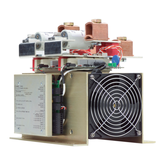
- Page 1 User’s Manual MaxPac PK480-5 0037-75428 June 2018...
- Page 3 ® price and performance. For more than 100 years, customers have relied on Chromalox for the utmost in quality and innovative solu- tions for industrial heating applications. Chromalox manufactures the world’s largest and broadest line of electric heat and control products.
-
Page 4: Table Of Contents
Table of Contents Section Topic Page 1..........Important Safeguards ..................3 2..........Description ..................... 4 3..........Before You Install .................... 5 4..........Installation ...................... 6 4.1 ......... Mounting ......................8 4.2 ......... Wiring ......................11 4.2.1 ..... Touch-Safe Design ..................11 4.2.2 ..... -
Page 5: Important Safeguards
Damage Prevention Messages: You will see other IMPORTANT messages that are proceeded by the word CAUTION that are intended to help prevent damage to the MaxPac™ or other equipment. Note that Damage Prevention Messages are NOT accompanied by the Safety Alert Symbol. -
Page 6: Description
MaxPac I, II, and III The Chromalox Model MaxPac IP, I, II and III Series are specifically designed for the OEM market. The Chro- malox MaxPac I, II and III controllers are highly versatile SCR Power Paks. Firing modes includes On/Off and DOT proportional zero voltage switching. -
Page 7: Before You Install
CARRYING OUT THE WORK DETAILED BELOW Immediately after receiving your MaxPac I, II, III or IP Series Controller, visually inspect the shipment packag- ing and record any damage on the shipping documents. Unpack the controller and carefully inspect for obvi- ous damage due to shipment. -
Page 8: Installation
Installation The forced air design of the MaxPac series allows The output power can only be connected from one mounting in any direction. It is essential that air flow direction. The three mounting configurations are through the enclosure be planned to insure proper shown below (MaxPac II Three-Phase Two-Leg cooling. - Page 9 Examples of Proper Air Flow Since hot air rises naturally, it is not recommended that cooling air enter from the top and exhaust at the bot- tom of the enclosure. Louvers Louvers MaxPac Enclosure Filter Forced Air In (Recommended) Pagoda Top...
-
Page 10: Mounting
3. 120 or 230 VAC 50/60hz for instrument power. See 4.2.4, pg. 16. 4.1 - Step 1: Mounting Before mounting your MaxPac, please read the section titled “Before You Install’ on page 5 for a description of an ideal environment for the unit’s operation. - Page 11 4.2" [107mm] 0.0" [0mm] 1.0" [25mm] Ø0.280" [Ø7.11mm] 4.7" [107mm] (6 HOLES) 0.0" [0mm] 1.0" [25mm] FIRING PACKAGE Ø0.280" [Ø7.11mm] FIRING PACKAGE (6 HOLES) 7.2" [184mm] 4.75" [121mm] 8.5" [216mm] 13.5" [342mm] 9.5" [241mm] 14.5" [368mm] FAN END FAN END 6.0"...
- Page 12 11.7" [298mm] 5.8" [148mm] 0.0" [0mm] 0.0" [0mm] 1.3" [33mm] 1.3" [33mm] Ø.3125" [Ø7.94mm] Ø.3125" [Ø7.94mm] (8 HOLES) (8 HOLES) 5.3" [135mm] 6.3" [160mm] FIRING PACKAGE FIRING PACKAGE 9.3" [237mm] 11.3" [28mm] 13.31" [338mm] 14.62" [371mm] 16.3" [414mm] FAN END 17.6"...
-
Page 13: Wiring
Electrical Code and any local standards that may be applicable. 4.2.1 - Touch-Safe Design If the MaxPac model you purchased is of a Touch-Safe design, follow the steps on the following page to install the electrical wiring. This will ensure the wiring is done properly while maintaining the Touch-Safe feature. -
Page 14: Cover Removal And Installation
Tighten all thumb screws. 4.2.3 - Line/Load Power Wiring The following illustrations depict how to connect the MaxPac to a resistive load. Make sure you refer to the correct illustration for the MaxPac series you have purchased. For the power/load drawings: On open design units up to 300 Amps, X1, X2, X3, L1, L2, and L3 refer to copper lugs. - Page 15 MaxPac II Three Wire MAX PAC II 2 Leg Control L2 Connection is NOT on MaxPac MaxPac III Four Wire 3 Leg Control MAX PAC III N Connection is NOT on MaxPac CAUTION IMPORTANT: The I t fuses installed on the SCR are designed to protect the SCR from faults on the load connection side.
- Page 16 Single Phase MAX PAC IP transformer Coupled L2 connection to MaxPac is instrument power only CAUTION IMPORTANT: The I t fuses installed on the SCR are designed to protect the SCR from faults on the load connection side. They are NOT intended to provide wire protection.
- Page 17 The following drawings show proper installation of the crimp lugs on the bus bars: All bolts must mount with excess bolt lengths Illustration 1: View From Rear Ventilated Panel toward the fuse to main- tain required electrical clearances. LOAD BUS BAR 1/0 through 500 mcm wire must mount on the fuse side of the bus...
-
Page 18: Instrument Power
(side away from the fuse) with the bolt extending toward the fuse. Flat washers should be used on both the bolt head and the nut and a lockwasher should be under the nut. The Touch Safe MaxPac is designed to allow both input and output wiring to enter/exit in either direction. -
Page 19: Command Signal Wiring
J2 pins 6 & 7 (4-20 mA) **Instrument power 4 VA maximum MaxPac I, II, and III On/Off Control Signals AC Input – The 120 – 230 VAC signal lines are connected to terminal J1-7 & 8. An input voltage of 120 to 230 VAC turns the power On. - Page 20 Illustration 3 Auto/Manual Input The MaxPac I, II and II can be wired to make it possible to select an input from either a temperature/ process controller or a manual input potentiometer. A switch is used to select between the input from a 1K potentiometer or a linear control input (see input connections).
- Page 21 The drive signal to the SCR trigger boards: The temperature alarm: The heat sink temperature is derived from a resistive temperature detection (RTD) sensor mounted on the heat sink. This is then compared to two set points. The first alarm is a warning and activates the externally connected device. This allows time to correct the problem before the second alarm inhibits the firing circuit.
- Page 22 Analog inputs: 4-20mA (or 0-20mA), 0-5Vdc (or 1-5Vdc), 0-10V • Digital ON/OFF inputs: AC ON/OFF, DC ON/OFF To select between any of these inputs, set the MaxPac as indicated in the table below: Input Command Select Method of Selection Potentiometer Select MANUAL mode by leaving no connection between J2.4 &...
- Page 23 Position Selection Note Reserved for factory use Do Not Use this Selection DOT for MXPCI Caution: Do not choose this setting if your unit is a MXPCII or MXPCII type DOT for MXPCII Caution: Do not choose this setting if your unit is a MXPCI or MXPCII type DOT for MXPCIII Caution: Do not choose this setting if your unit is a...
- Page 24 Remote Stop When it is necessary to disable or enable the output, connect a dry contact between J3 – 3 & 4. When it is closed, the power control will disable the output. CAUTION IMPORTANT: This stop overrides the control input only. It will NOT protect against faulted or damaged SCRs.
- Page 25 Input Terminals (MaxPac I, II, and III): FIG 1 FIG 2 FIG 3 SHORTED SCR INDICATOR HI TEMP INDICATOR These are AC voltage outputs at 100 mA max., not contact closures. See model number 120-230 INSTRUMENT POWER for voltage rating...
- Page 26 N.C. contacts. Start-up The MaxPac IP has been factory calibrated for 4 - 20mA input. Be sure the operating voltage and signal input are correctly applied. Also, make sure the Emergency Stop, if used, has N.O. contacts and jumper pins 4 &...
-
Page 27: Calibration
“high starting currents” may exist for extended periods of time. Generally, once the elements have achieved their normal operat- ing temperatures, the current drawn through the MaxPac Power Pak will fall within the rating of the unit. For these types of loads, we recommend adjusting the I LIM (Current Limit) to 50% or less. - Page 28 Controller Configuration...
-
Page 30: Specifications
Specifications MaxPac I, II, and III Control Inputs Line Voltage ....120 - 575 VAC, 60 Hz Accepts all of the following as standards: CE 400 VAC 50 Hz Load Current Rating ..100, 150, 200, 300, 400, On/Off Control 550, 650, 800, 1000, 1200A Signal Input 120 thru 230 VAC ±... -
Page 31: Maintenance
Maintenance READ AND UNDERSTAND BEFORE CARRYING OUT THE WORK DETAILED BELOW WARNING Hazardous Voltage: Disconnect all power before performing any maintenance or examining the power module. Exposed terminals may carry LETHALLY HIGH VOLTAGES when power is applied. Environmental Issues: Temperature: When mounting the SCR unit in a control panel attention should be paid to the enclosure temperature. -
Page 32: Troubleshooting
READ AND UNDERSTAND BEFORE CARRYING OUT THE WORK DETAILED BELOW The following guidelines cover most of the common problems that could occur with the MaxPac. They are not intended to be, nor can they be, absolutes to cover every possible failure. -
Page 33: Parts And Accessories
SKKT500 0002 - 47557 0029 - 00814 44 inch/lb (5 Nm) 106 inch/lb (12 Nm) MaxPac I, II, and III Accessories: Part Number Description 0135 - 28193 SCR Trigger Board 0135 - 28194 On/Off Main Firing Board 0135 - 20117 Potentiometer & Remote/Manual Switch... -
Page 34: Warranty And Return Information
Returns Items returned to Chromalox must be accompanied by a Return Authorization Number. This number may be obtained from Chromalox’ Customer Service Department at the phone number listed below. - Page 35 Ordering Information for MaxPac I Model SCR Power Pack MXPC I Single Phase SCR Power Pack Code Control Configuration Proportional Control, DOT Zero-Crossover Firing, Command Input Signals: 4-20mA, 0-5 VDC, 1-5 VDC (via Modbus RTU/485 only), 0-10 VDC, Remote 0-1000 OHM Potentiometer w/Manual Override, Modbus RTU/RS485 Communications.
- Page 36 Ordering Information for MaxPac I (continued) Code Fusing Option (1) For < 500VAC Applications, Select One None 100 -150 Amp PAK (200 Amp Fuse) 200 Amp PAK (250 Amp Fuse) 300 Amp PAK (400 Amp Fuse) 400 Amp PAK (500 Amp Fuse)
- Page 37 Ordering Information for MaxPac IP Model SCR Power Pack MXPC IP Single Phase SCR Power Pack Code Control Configuration Phase Angle Control (Accepts: 0-5 mA, 0-20 mA, 0-50 mA, 1-5mA, 4-20 mA, 10-50 mA, 0-5Vdc, 0-10 VDC) Phase Angle Control with Current Limit Code Current at 50°C (122°F)
- Page 38 Ordering Information for MaxPac IP (continued) Code Fusing Option (1) For < 500VAC Applications, Select One None 100 -150 Amp PAK (200 Amp Fuse) 200 Amp PAK (250 Amp Fuse) 300 Amp PAK (400 Amp Fuse) 400 Amp PAK (500 Amp Fuse)
- Page 39 Ordering Information for MaxPac II Model SCR Power Pack MXPC II Three Phase SCR Power Pack Code Control Configuration Proportional Control, DOT Zero-Crossover Firing, Command Input Signals: 4-20 mA, 0-5 VDC, 1-5 VDC (via Modbus RTU/485 only), 0-10 VDC, Remote 0-1000 OHM Potentiometer w/Manual Override, Modbus RTU/RS485 Communications.
- Page 40 Ordering Information for MaxPac II (continued) Code Fusing Option (1) For < 500VAC Applications, Select One None 100 -150 Amp PAK (200 Amp Fuse) 200 Amp PAK (250 Amp Fuse) 300 Amp PAK (400 Amp Fuse) 400 Amp PAK (500 Amp Fuse)
- Page 41 Ordering Information for MaxPac III Model SCR Power Pack MXPC III Three Phase Six SCR Power Pack Code Control Configuration Proportional Control, DOT Zero-Crossover Firing, Command Input Signals: 4-20 mA, 0-5 VDC, 1-5 VDC (via Modbus RTU/485 only), 0-10 VDC, Remote 0-1000 OHM Potentiometer w/Manual Override, Modbus RTU/RS485 Communications.
- Page 42 Ordering Information for MaxPac III (continued) Code Fusing Option (1) For < 500VAC Applications, Select One None 100 -150 Amp PAK (200 Amp Fuse) 200 Amp PAK (250 Amp Fuse) 300 Amp PAK (400 Amp Fuse) 400 Amp PAK (500 Amp Fuse)
-
Page 43: Ec Declaration Of Conformity
Electromagnetic Compatibility Directive (2004/108/EC) based on its design and type, as brought into circula- tion by us. In case of alteration of the machine, not agreed upon by us, this declaration will lose its validity. Description of the Electrical Equipment: MaxPac SCR controllers Model Number: MaxPac Series; MaxPac I, II, III... - Page 44 Filters Required: Instrument power filter: 10. Surge Immunity Chromalox P/N 0005-60057 EN 61000-6-2:2005 / EN 61000-4-5:1995 Line Filter, single phase: Chromalox P/N 0005-60055 Line Filter, three phase: Chromalox P/N 0005-60056 The Technical documentation required by Annex IV (3) of the Low Voltage Directive is maintained by (Name)
Need help?
Do you have a question about the MaxPac and is the answer not in the manual?
Questions and answers