Table of Contents

Summary of Contents for philippi PSM 2
- Page 1 System Monitor PSM 2 INSTRUCTION MANUAL System Monitor PSM 2 philippi elektrische systeme gmbh www. philippi-online.de Neckaraue 19 info@philippi-online.de D-71686 Remseck am Neckar Tel: +49 7146 8744-0, Fax-22 REV 1A – Software V3 Page 1...
-
Page 2: Table Of Contents
System Monitor PSM 2 1 Safety references 1.1 Exclusion of liability 1.2 Warranty 1.3 CE Conformity 2 Content 3 Technical data 4. Installation 4.1 Necessary equipment 4.2 Installation and connection of the PSM2 4.3 System arrangement PBUS 5 Quick operation Start-Up of the PSM2 5.1 Password protection (PIN) of the Setup menu... -
Page 3: Safety References
System Monitor PSM 2 The System Monitor PSM2 is designed for the supervision and control of all philippi components that are connected to the PBUS system. It is the main display and operational interface, and the electrical system can be supervised, operated and controlled using the PSM2 system monitor. -
Page 4: Ce Conformity
System Monitor PSM 2 1.3 CE Conformity philippi elektrische systeme gmbh certifies herewith, that the System Monitor PSM2 fulfils the requirements of the European Regulation: 2004/108/EG “Electromagnetic compatibility” The compatibility of the device is certified by the CE-sign. 2 Content... -
Page 5: Installation And Connection Of The Psm2
System Monitor PSM 2 4.2 Installation and connection of the PSM2 Install the PSM2 in a dry and visible place, so that it can be read off at any time. The necessary installation cut out is 88 x 88mm (3.5” x 3.5”), the necessary minimum depth is 40mm (1.6”). -
Page 6: Quick Operation Start-Up Of The Psm2
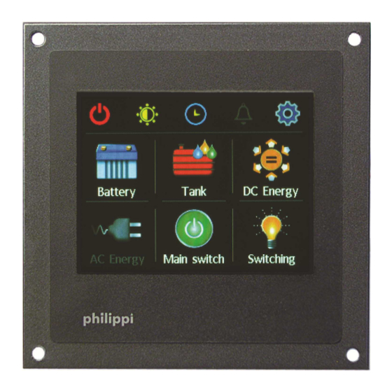
System Monitor PSM 2 5 Quick operation Start-Up of the PSM2 On the large illuminated colour touch screen display, information of the available systems is displayed and operation and adjustments are possible. If a device is connected to the network and activated, details will be shown in the appropriate sub menu. -
Page 7: Identification Of All Devices Connected To The Pbus
System Monitor PSM 2 5.2 Identification of all devices connected to the PBUS In the Setup menu, press “Display”, and on the next page press the arrow in the top right-hand of the screen to go to page 2. On page 2, pressing “Connected Devices”... -
Page 8: Setup „Display
System Monitor PSM 2 6.1 Setup „Display “ Language Please choose your language. Brightness operation You can adjust the brightness of the display illumination while in operation from 20 to 100 %. Brightness Day You can adjust the brightness of the display illumination in the normal mode from 20 to 100 %. -
Page 9: P-Bus Network
System Monitor PSM 2 6.2 P-BUS Network This configuration can delete the whole system so only the system integrator is allowed to carry it out! Logged devices This shows the devices which are or were connected to the PBUS network at the time of the last scan of connected devices. -
Page 10: Data Logging
System Monitor PSM 2 6.3 Data Logging If there is an SIM card inserted into the PSM2 this function is activatable. With this function, you can record all the measurable data and analyse them on your PC later. A new folder is created for each measurable parameter. -
Page 11: System Time
System Monitor PSM 2 Off: For this device the alert notification is turned off and no alarm will be displayed /reported. Message: For this device the alert notification will be displayed in form of a report Message For this device the alert notification will be shown on the display as a... - Page 12 System Monitor PSM 2 In this Submenu, the following settings are possible: Load configuration from SD card A previously saved configuration can be loaded from the SD-Card Save configuration to SD card The actual configuration is stored on the SD-Card...
-
Page 13: Operation
System Monitor PSM 2 After entering the consumer page, the buttons will appear according to the programming. Through pressing the screen button, the consumer will turn ON or OFF. 7. Operation In the main menu, the subitems are active which are connected and able to receive data. -
Page 14: Submenu Battery
System Monitor PSM 2 7.1 Submenu battery Needed interface / component: SHC 312 / SHC 612 / EM-box. A maximum of 4 batteries or battery banks are displayed per page. Further batteries can be displayed on subsequent pages. The pages can be changed by pressing the arrow buttons at the top. -
Page 15: Submenu Tank
System Monitor PSM 2 7.2 Submenu Tank Needed interface/component: CMT2 7.2.1 Features of Tanks By touching on one of the tank graphics, the volume indication changes between percentage, litres, and a no-volume display. If a tank is configured for a DFS Flow Sensor, the percentage volume can be changed manually to the new level by tapping on the name of the tank underneath the graphic. -
Page 16: Troubleshooting Tank Sensors
System Monitor PSM 2 7.2.3 Troubleshooting tank sensors If the tank monitor shows wrong values or “---“, first check that the sensor is connected properly. Next check the wiring between the sensor and the tank interface CMT2, as this has shown to be the main source of errors. -
Page 17: Battery Charger Ace
System Monitor PSM 2 7.3.2 Battery Charger ACE In the Charger menu, the parameters of the automatic charger ACE are shown. By touching the buttons “Limit+”, “Limit- “and “Sleep”, the corresponding operational modes can be adjusted. 7.4 Submenu main switch... -
Page 18: Submenu Ac (Lau)
System Monitor PSM 2 7.5 Submenu AC (LAU) Needed interface/component: LAU 216 / 3xx This menu shows the energy situation of the AC system, where the symbols on the top line show the available sources. If these sources are active, the voltage is shown. -
Page 19: Temperature
System Monitor PSM 2 7.7 Temperature Needed interface/component: TPC4 This screen shows the temperatures of the individual sensors. By pressing on the temperature button you can receive further data as highest/lowest temperature with a time stamp. 7.8 Consumer Needed interface/component: CMR4 By pressing the screen button, the consumer is turned on or off. -
Page 20: Software Update
System Monitor PSM 2 8. Software Update The software of the PSM2 can be updated by means of a micro-SD card. After having received the software by e-mail, the files need to be copied onto an empty SD-card. First, remove the power supply plug of the PSM2 and insert the SD-card at the slot of the right hand side of the rear cover.
Need help?
Do you have a question about the PSM 2 and is the answer not in the manual?
Questions and answers
How do I reset the Phillippi system monitor to factory reset
To perform a factory reset on the Philippi PSM 2 system monitor, press the "PIN" button on the first page of the Setup menu and hold it for at least 15 seconds. This will reset the PIN to the factory default setting of "1234".
This answer is automatically generated
How do I reset the battery to register
To reset the battery on the Philippi PSM 2, remove the rear lid, take out the installed battery (CR2032-3V) from its holder, and replace it with a new one.
This answer is automatically generated