
Related Manuals for Omnik New Energy Co., Ltd. Omniksol-13k-TL

Summary of Contents for Omnik New Energy Co., Ltd. Omniksol-13k-TL
- Page 1 User Manual V3.1 User Manual -Installation -Operation Omniksol-13k-TL Omniksol-17k-TL Omniksol-20k-TL Omnik New Energy Co.,Ltd.
-
Page 3: Table Of Contents
User Manual V3.1 Catalog Notes on this manual ..........................3 General notes ............................3 Symbols Used ............................3 Target Group............................4 Preparation ..............................5 Safety Instructions ..........................5 Explanations of Symbols on Inverter ....................7 Product Information ..........................8 Overview .............................. 8 Major Characteristics ........................... - Page 4 User Manual V3.1 7.2.2. Parameters ............................. 35 7.2.3. Tools & Options ..........................37 7.2.4. Information ............................41 7.2.5. Error ..............................42 7.2.6. Update ............................43 State Information ..........................43 Monitoring system ..........................45 Recycling and Disposal ......................... 47 10. Troubleshooting ............................. 48 11.
-
Page 5: Notes On This Manual
The main purpose of this User’s Manual is to provide instructions and detailed procedures for installing, operating, maintaining, and troubleshooting the following three types of Omnik New Energy-Solar Inverters: Omniksol-13k-TL Omniksol-17k-TL Omniksol-20k-TL Please keep this user manual all time available in case of emergency. -
Page 6: Target Group
User Manual V3.1 1.3 Target Group Chapter 1, 2, 3, 4, 7, 8, 9, 10 and Chapter 11 are intended for anyone who is intended to use Omnik Grid Tie Solar Inverter. Before any further action, the operators must first read all safety regulations and be aware of the potential danger to operate high- voltage devices. -
Page 7: Preparation
User Manual V3.1 2. Preparation 2.1 Safety Instructions DANGER DANGER due to electrical shock and high voltage DO NOT touch the operating component of the inverter, it might result in burning or death. TO prevent risk of electric shock during installation and maintenance, please make sure that all AC and DC terminals are plugged out. - Page 8 User Manual V3.1 NOTICE Public utility only The PV inverter designed to feed AC power directly into the public utility power grid,do not connect AC output of the device to any private AC equipment. CAUTION The PV inverter will become hot during operation; please don’t touch the heat sink or peripheral surface during or shortly after operation。...
-
Page 9: Explanations Of Symbols On Inverter
User Manual V3.1 2.2 Explanations of Symbols on Inverter Symbol Description Dangerous electrical voltage This device is directly connected to public grid, thus all work to the inverter shall only be carried out by qualified personnel. DANGER to life due to high electrical voltage! There might be residual currents in inverter because of large capacitors. -
Page 10: Product Information
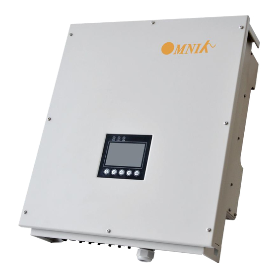
User Manual V3.1 3. Product Information 3.1 Overview Industrial Layout Excellent Heat Elimination Effective Shield For DC/AC/Communication Connections... -
Page 11: Major Characteristics
RS485, Ethernet and USB communication. • Transformer less design and high power density, it is lighter and more convenient for installation. 3.3 Technical Data Type Omniksol-13k-TL Omniksol-17k-TL Omniksol-20k-TL Input(DC) Max.PV-Generator Power[W] 13500 17600 21200 Max DC Voltage[V]... - Page 12 User Manual V3.1 Standby[W] Efficiency Max. Efficiency 98,1% 98.2% Euro Efficiency 97.5% 97.6% 97.8% MPPT Efficiency 99.9% 99.9% 99.9% Safety and Protection Type Ⅲ Type Ⅲ Type Ⅲ DC Surge Protection DC Insulation Monitoring Integrated Integrated Integrated Earth Fault Protection Integrated Integrated Integrated...
-
Page 13: Packing Checklist
User Manual V3.1 4. Packing checklist 4.1 Assembly parts After you receive the Omnik inverter, please check if there is any damage on the carton, and then check the inside completeness for any visible external damage on the inverter or any accessories. -
Page 14: Product Appearance
User Manual V3.1 Ground nut (M6) Cord end terminal Screw (M4X12) 4.2 Product Appearance Front Object Description LED light(Green) – RUN LED light(Red) – FAULT LED light(Yellow) – COM < left choice > Right choice ∧ up choice ∨ down choice Ok identify key... - Page 15 User Manual V3.1 Bottom Left and right...
-
Page 16: Product Identification
User Manual V3.1 Object Description DC switch Plug connectors for DC input. RS232 interface RS485 interface Earthing Ethernet interface USB interface Terminal for grid connection (AC output) Update and reset switch for display 4.3 Product Identification You can identify the inverter by the side nameplate. Information such as serial number (SN.), type of the inverter, as well as inverter specifications are specified on the side name plate. -
Page 17: Installation
Installation directly expose under intensive sunshine is not recommended. The installation site MUST have good ventilation condition. 5.2 dimensions, weight Model weight Dimension (L×W×D) Omniksol-13K-TL 44.5kg 575mm×650mm×240mm Omniksol-17K-TL 45kg 575mm×650mm×240mm Omniksol-20K-TL 45kg 575mm×650mm×240mm... -
Page 18: Mounting Instructions
User Manual V3.1 5.3 Mounting Instructions Omnik inverter is designed for indoors and outdoors installation Please mount the inverter in the direction as illustrated above Install the inverter in the vertical direction is recommended, with a max.15 degrees backwards. -
Page 19: Safety Clearance
User Manual V3.1 5.4 Safety Clearance Observe the following minimum clearances to walls, other devices or objects to guarantee sufficient heat dissipation and enough space for pulling the electronic solar switch handle. 30cm 30cm Direction Minimum clearance Above 20 cm Below 30 cm Sides... - Page 20 User Manual V3.1 2) First, according to the marks, drill 4 holes in the wall. Then, place four expansion tubes in the holes using a rubber hammer. Next, wring 4 screws into the expansion tubes.
- Page 21 User Manual V3.1 3) First check the 4 holes in the backside of the inverter. Then, lift the inverter carefully, align the 4 holes in the inverter and the 4 screws in the wall, and finally attach the inverter to the screws slightly.
-
Page 22: Electrical Connection
User Manual V3.1 6. Electrical Connection 6.1 Safety DANGER DANGER to life due to potential fire or electricity shock. With the inverter powered, comply with all prevailing national regulations on accidents prevention. This inverter will be directly connected with HIGH VOLTAGE power generation device, the installation must be performed by qualified personnel only in compliance with national and local standards and regulations. -
Page 23: Dc Side Connection
User Manual V3.1 Object Description DC switch Plug connectors for DC input. RS232 interface RS485 interface Earthing Ethernet interface USB interface Terminal for grid connection (AC output) 6.3 DC Side Connection DANGER DANGER to life due to potential fire or electricity shock. NEVER connect or disconnect the connectors under load. - Page 24 User Manual V3.1 For Omniksol-13k-TL ,Omniksol-17k-TL and Omniksol-20k-TL, there are two MPP Tracker, and the DC characteristics of them are illustrated as the following table. Max. DC Max. DC Max. DC Inverter Type Tracker Power Voltage Current Omniksol-13k-TL 13500W 22/11A...
- Page 25 User Manual V3.1 5) Insert contact cable assembly into back of the male and female connector. A “click” should be heard or felt when the contact cable assembly is seated correctly. 6) Wrest the cap by using the torque of 2.6~2.9NM. 7) After wrest the cap tightly, align the 2 half connectors and mate them together by hand until a “click”...
-
Page 26: Ac Side Connection
User Manual V3.1 10) Please use sealing caps for tight sealing of unplugged PV connectors. If using H4 connector, the operating procedure is similar as that of MC4 connector. 6.4 AC side connection DANGER DANGER to life due to potential fire or electricity shock. NEVER connect or disconnect the connectors under load. - Page 27 User Manual V3.1 2) Insert the striped cable into cord end terminal and insert the assembly into barrel. Then the line will like the picture belows. 3) Insert the finished 5 lines into AC cover assembly with the following sequence: Open the plastic cover, use slot type screwdriver to press the shrapnel in the indicated position, and then put the line in the right hole, please note the sequence of the line shall in the right order: L1,L2,L3,N,PE...
- Page 28 User Manual V3.1 Cover the assembly, tightly screwed and then screw the cable gland...
-
Page 29: Communication And Monitoring Connector
User Manual V3.1 6.5 Communication and Monitoring connector There are RS232/RS485, Ethernet and USB interface in the bottom side of the Omnik inverter as the following figure: The function is as below: Object Description Function Update the Software RS232 interface Version of the inverter RS485 interface Connect with PMB... -
Page 30: Display
User Manual V3.1 7. Display 7.1 Main interface Object Description Time (e.g.2011-12-09 10:44) Current date and time Safety(e.g. Portugal) Current safety regulation selected Operation (e.g. normal ) Current operation condition The energy generated today in kilo watt hours E-today (kWh) The energy generated since starting up the E-total inverter (kWh) -
Page 31: Lcd Display
User Manual V3.1 NOTICE Omnik inverter is not an aligned measuring instrument for current, voltage or power consumption. A slight deviation of a few percent points is intrinsic to the system, the results from the inverter cannot be used for grid balance calculations. -
Page 32: Curve
User Manual V3.1 7.2.1. Curve a. P-Now Draw curve of current power: Click “Curve”----“P-Now”... - Page 33 User Manual V3.1 b. P-Day Draw curve of one day’s power: Click “Curve”----“P-Day”...
- Page 34 User Manual V3.1 c. E-Month Show one month’s generated energy: Click “Curve”----“E-Month”...
- Page 35 User Manual V3.1 d. E-Year Draw curve of one year’s generated energy: Click “Curve”----“E-Year”...
- Page 36 User Manual V3.1 e. E-Total Draw curve of every year’s generated energy: Click “Curve”----“E-Total”...
-
Page 37: Parameters
User Manual V3.1 7.2.2. Parameters a. AC Parameters Show AC parameter: Click “Actual Value”---“AC Actual Value”... - Page 38 User Manual V3.1 b. DC Parameters Show DC parameter, including following items: Vpv (1-2),Ipv(1-2) Click“Actual Value”---“DC Actual Value”...
-
Page 39: Tools & Options
User Manual V3.1 7.2.3. Tools & Options a. Language and Time Setting of language & time Click“Setting”----“Language and Time”... - Page 40 User Manual V3.1 b. Safety Parameters Setting of safety parameters: Click“Setting”----“Safety Parameters”。...
- Page 41 User Manual V3.1 c. Clear Data Clear Log: Click“Setting”----“Clear Data”...
- Page 42 User Manual V3.1...
-
Page 43: Information
User Manual V3.1 7.2.4. Information Device Info Kinds of inverter:20K/17K/13K Vision number & serial number: Click“Information”----“Device Info”... -
Page 44: Error
User Manual V3.1 7.2.5. Error Error Info Show Error information: Click“Error”----“Error Info”... -
Page 45: Update
User Manual V3.1 7.2.6. Update Flash It’s used for updating invertors’ Firmware. After putting invertor’s ROM documents to related catalogue, users can update the Firmw are by clicking the button. 7.3 State Information State Display State information Waiting Initialization & waiting Wait Connect Sec. - Page 46 User Manual V3.1 AC Voltage Out of AC Voltage Out of Range Range Utility Loss Utility Loss GFCI Failure GFCI Failure PV Over Voltage PV Over Voltage Isolation Fault Isolation Fault Fan Lock Fan Lock Over Temperature Over Temperature in Inverter in Inverter Consistent Fault:Vac differs...
-
Page 47: Monitoring System
User Manual V3.1 8. Monitoring system • System configuration: The system consists of Grid、Radio Ripple Control receiver、 PMB、Inverter、Battery pack and so on(view picture above for reference). • Introduction of sub-element: 1) PMB (Power Management Box)is core of the system. It’s used for managing power and monitoring working status of inverter. - Page 48 User Manual V3.1 • Working principle of the system: The omniksol inverter can be connected to the PMB (Power Management Box) via its RS485 interface, the maximum of the quantity is 20 sets three-phase inverter. Inside the PMB, a web server is integrated in, customers can view or check the detailed information about their inverter by login on a IP address of PMB, (for example: http://192.168.16.48/index.asp), the information including but not limited to total quantity of the inverters, gross generation, generation for today, as well as all the parameters of each inverter...
-
Page 49: Recycling And Disposal
User Manual V3.1 9. Recycling and Disposal To comply with European Directive 2002/96/EC on waste Electrical and Electronic Equipment and its implementation as national law, electrical equipment that has reached the end of its life must be collected separately and returned to an approved recycling facility. Any device that you no longer required must be returned to your dealer or you must find an approved collection and recycling facility in your area. -
Page 50: Troubleshooting
User Manual V3.1 10. Troubleshooting LCD display Possible actions 1. Check the impedance between PV (+) & PV (-) and the inverter is earthed. The impedance must Isolation Fault be greater than 2.4M. 2. Check whether the AC-side has contacts with earth. - Page 51 User Manual V3.1 Consistent Fault: Fac differs for M-S Disconnect PV (+) or PV (-) from the input, restart Vac differs for M-S the inverter. Fac, Vac Differs for M-S Ground I differs for M-S DC inj. differs for M-S AC Relay Check Fail High DC bus Permanent...
-
Page 52: Warranty
Terms and Conditions Omnik offers 60 months from the date of purchase from retailer for Omniksol-13k-TL / 17k-TL / 20k-TL on-grid inverters, subject to the conditions listed below. Please note that this does not apply for the accessories. If a product is suspected of being defective during the specified Omnik factory warranty period then Omnik will initially perform a pre-qualification of the issue. -
Page 53: Abbreviation
User Manual V3.1 12. Abbreviation Liquid Crystal Display Light Emitting Diode MPPT Maximum Power Point Tracking Photovoltaic Voltage at the DC side Voltage at the AC side Vmpp Voltage at the Maximum Power Point Impp Amperage at Maximum Power Point Alternating Current ( Form of electricity supplied by Utility Company ) Direct Current ( Form of electricity generated by PV modules ) -
Page 54: Contact
User Manual V3.1 13. Contact Suzhou Headquarter Xinghu Road No.218 bioBAY Park A4-314 215123 Suzhou China Tel: +86 512 6295 6676 Fax: +86 512 6295 6682 Email: info@omnik-solar.com www.omnik-solar.com Omnik German Service Center Omnik GmbH Forsthausstr.8A 65479 Raunheim Tel:+49 (179) 9762 654 Service line Tel: +86 512 6295 6676 Fax: +86 512 6295 6682...
Need help?
Do you have a question about the Omniksol-13k-TL and is the answer not in the manual?
Questions and answers