Advertisement
Quick Links
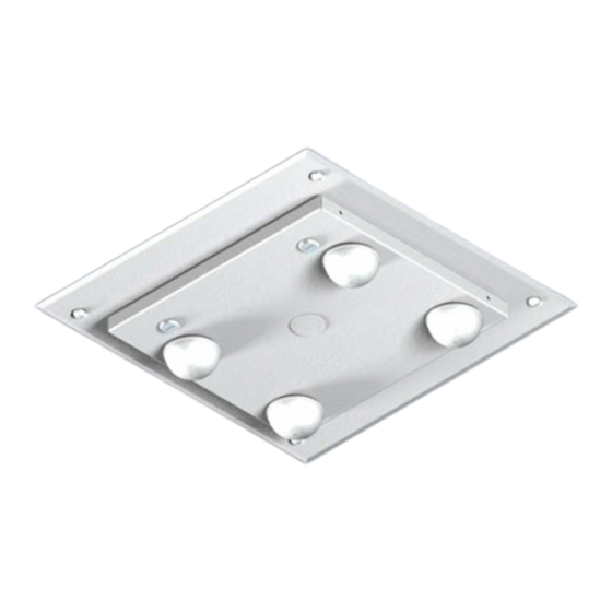
Assembly Components:
- Enclosure Model 1028-08-ANT5-B assembly – 1 each
- 1/2" Trade size hole plugs – 4 each
- 1" Trade size hole plugs – 3 each
- hanger wire – 8 each
- Installation Instructions – 1 each
- #8 Screws – 4 each
- Internal universal equipment mounting plate – 1 each
- Plastic screw head caps – 4 each
If any of these items are missing, contact your Oberon representative.
Find a flat work surface to assemble the enclosure and any other network/cellular components prior to mounting in ceiling.
Step 1 – Place the enclosure assembly back side down on the work surface and keyed doorway unlocked.
**IMPORTANT** - Determine the correct access point installation method based on the manufacturer.
Step 2a – (For Cisco AP's Only) The mounting holes for Cisco AP's are located in the mounting plate. Standard Cisco mounting brackets
as well as "Bracket 2" can be attached so the "Cisco" logo of the AP is parallel to the hinge. For "Bracket 1" the logo of the AP will be
mounted perpendicular to the hinge. Securely fasten the access point's mounting plate to the mounting holes on the mounting plate of the
enclosure using four (4) # 8 screws. Attach the Access Point to the mounting plate (Figure 1).
Figure 1
Page 2
Rev. A2 01/24/14
Installation Instructions
Model Number 1028-08-ANT5-B
Step 3 – (Optional) With the desired number of holes opened, attach antennas
(such as Oberon's BMANT or DMDUAL) and DAS antennas by inserting the
cables through the door holes. Fasten the antennas to the door per the antenna
manufacturer's instructions. To retain the water and dust resistance of the
enclosure, antennas should have a gasket to fill the opening. After installation,
connect the RF coax cable from the antenna to the access point (Figure 3). If
using Bulkhead connectors, use Oberon Bulkhead connectors with provided o-
ring (P/N 35-NFBLKHD) to maintain water tightness.
The assembled unit is now ready for ceiling or wall installation.
Page 3
(877) 867-2312 • www.oberonwireless.com
Oberon, Inc. • • • • 1315 South Allen Street • • • • State College, PA 16801
Step 2b – (Any manufacturer's access points) Install the provided
"T-Bar" bracket by fastening two (2) #8 screws into the enclosure
mounting plate. Attach the access point to the T-Bar bracket using
the manufacturer's instructions for attaching the access point to a
ceiling tile grid (T-Bar). (Figure 2).
Figure 2
Figure 3
Copyright 2013
Advertisement

Related Manuals for OBERON 1028-08-ANT5-B


Summary of Contents for OBERON 1028-08-ANT5-B
- Page 1 The assembled unit is now ready for ceiling or wall installation. Figure 1 Figure 3 Page 3 Page 2 (877) 867-2312 • www.oberonwireless.com Rev. A2 01/24/14 Oberon, Inc. • • • • 1315 South Allen Street • • • • State College, PA 16801 Copyright 2013...
-
Page 2: Installation Instructions
Acoustical, suspended, false, drop and Be sure to use appropriate hardware for the wall construction concealed spline ceiling grid work is not designed to support the weight of this product. Oberon’s ceiling mounted type. (Reference Figure 4) products have four support wire tabs on the back box.
Need help?
Do you have a question about the 1028-08-ANT5-B and is the answer not in the manual?
Questions and answers