Table of Contents
Advertisement
Advertisement
Table of Contents

Summary of Contents for ARTEX DGL-1
- Page 1 DGL-1 (Dongle) Programming Adapter 453-4010 Description, Operation, Installation and Maintenance Manual 570-4010 Rev. G Artex Products / ACR Electronics, Inc. 5757 Ravenswood Road, Fort Lauderdale, FL 33312 Phone (954) 981-3333, Fax (954) 983-5087 www.acrartex.com...
- Page 2 ARTEX PRODUCTS / ACR ELECTRONICS, INC. DESCRIPTION, OPERATION, INSTALLATION AND MAINTENANCE MANUAL DGL-1, DONGLE (453-4010) PROPRIETARY INFORMATION This document contains proprietary information and such information may not be disclosed to others for any purpose, nor used for manufacturing purposes without written permission from ACR Electronics.
-
Page 3: Table Of Contents
INTRODUCTION ............................9 Manual Usage ..........................9 General ..........................9 Application ..........................9 Model Descriptions ........................10 Dongle DGL-1 Programming Adapter ..................10 Approvals ............................ 10 Dongle DGL-1 ........................10 References ..........................10 Regulatory Documents ......................10 Other Documents ......................... 10 DESCRIPTION AND OPERATION ...................... - Page 4 ARTEX PRODUCTS / ACR ELECTRONICS, INC. DESCRIPTION, OPERATION, INSTALLATION AND MAINTENANCE MANUAL DGL-1, DONGLE (453-4010) DGL-1 Programming Adapter ......................17 Dongle Removal ........................17 Material or Equipment Return ....................... 18 Shipment Information ......................18 Return Material Authorization....................18 INSTALLATION ............................19 Regulatory Requirements and Guidelines ..................
-
Page 5: List Of Acronyms, Abbreviations And Definitions
ARTEX PRODUCTS / ACR ELECTRONICS, INC. DESCRIPTION, OPERATION, INSTALLATION AND MAINTENANCE MANUAL DGL-1, DONGLE (453-4010) LIST OF ACRONYMS, ABBREVIATIONS AND DEFINITIONS Term Definition Advisory Circular – A Federal Aviation Administration (USA) bulletin with special information. For the purposes of this document, the acronym AC does not refer to electrical alternating current. -
Page 6: List Of Figures
DESCRIPTION, OPERATION, INSTALLATION AND MAINTENANCE MANUAL DGL-1, DONGLE (453-4010) LIST OF FIGURES Figure 1 DGL-1 (Dongle) Programming Adapter with ELT Cover ............10 Figure 2 DGL-1 (Dongle) Programming Adapter Assembly ..............11 Figure 3 Dongle Removal Sequence ....................17 Figure 4 Dongle Outline and Dimensions ................... 20 Figure 5 Dongle Wiring Harness Arrangement .................. -
Page 7: Record Of Revisions
ARTEX PRODUCTS / ACR ELECTRONICS, INC. DESCRIPTION, OPERATION, INSTALLATION AND MAINTENANCE MANUAL DGL-1, DONGLE (453-4010) RECORD OF REVISIONS REVISION CHANGE DATE REVISION CHANGE DATE RELEASE Nov 06/2002 DCN 2124 Dec 18/2002 DCN 2147 Feb 17/2003 DCN 2188 Apr 21/2003 DCN 2369... -
Page 8: Service Bulletin List
ARTEX PRODUCTS / ACR ELECTRONICS, INC. DESCRIPTION, OPERATION, INSTALLATION AND MAINTENANCE MANUAL DGL-1, DONGLE (453-4010) SERVICE BULLETIN LIST SERVICE ISSUE MANUAL MANUAL SUBJECT BULLETIN NO DATE REV NO REV DATE 570-4010 Rev. G Company Confidential Page 8 of 30... -
Page 9: Introduction
Adapter. This information is provided to ensure initial and continued airworthiness. Information presented in this manual is accurate at time of printing, but is subject to change. Refer to the Artex products web site at www.acrartex.com for the latest information and any updates to this manual. -
Page 10: Model Descriptions
C/S G.005, “Cospas-Sarsat Guidelines on 406 MHz Beacon Coding, Registration and Type Approval” b) C/S S.007, “Handbook of Beacon Regulations” B. Other Documents 1) The following documents are available on-line at the Artex products web site at www.acrartex.com, or from ACR Electronics upon request. 570-1000, “ELT Test Set (ETS) Operation Manual”... -
Page 11: Description And Operation
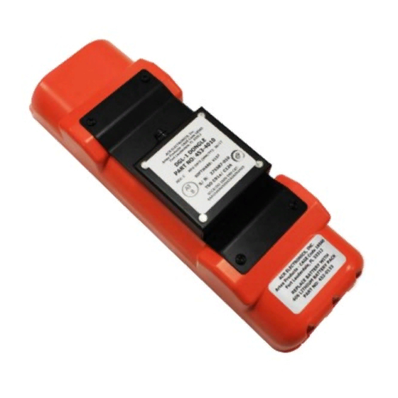
1) The Dongle is designed to mount to a protective top cover on the ELT with four screws. See Figure 2 DGL-1 (Dongle) Programming Adapter Assembly. Figure 2 DGL-1 (Dongle) Programming Adapter Assembly 2) The Dongle can be mounted directly to the airframe within the proximity of the ELT to utilize the prefabricated cable assembly (P/N 611-4010). -
Page 12: Operation
Protocol). NOTE: The Dongle is designed for use only with Artex ELTs. No other use of the Dongle is certified or approved by ACR Electronics. c) The ELT software version must be at least V133M, V134B, or V135C (displayed on the ELT product label). -
Page 13: Specifications
ARTEX PRODUCTS / ACR ELECTRONICS, INC. DESCRIPTION, OPERATION, INSTALLATION AND MAINTENANCE MANUAL DGL-1, DONGLE (453-4010) 3. Specifications A. Electrical 1) Table 1 lists the electrical specifications of the Dongle. CRITERIA PARAMETER CHARACTERISTIC Pin 1 RX Input Pin 2 TX Output Pin 3 5.6 VDC Output... -
Page 14: Test And Fault Isolation
ARTEX PRODUCTS / ACR ELECTRONICS, INC. DESCRIPTION, OPERATION, INSTALLATION AND MAINTENANCE MANUAL DGL-1, DONGLE (453-4010) TEST AND FAULT ISOLATION 1. General A. Applicability 1) This section only covers inspection, testing, and fault isolation procedures specific to the Dongle. 2) Refer to the applicable ELT Description, Operation, Installation & Maintenance Manual associated with the ELT to coordinate the requirements herein with the requirements for inspection, test, and fault isolation of the ELT system as a whole. -
Page 15: 15-Digit Hex Id Verification
Deactivate the ELT and read the test message broadcast at “turn-off”. NOTE: The ELT LED will flash 5 times to indicate a navigation data failure if an Artex Nav Interface Unit is not installed with the ELT. The Dongle does not support the position data function of the ELT. -
Page 16: Fault Isolation
ARTEX PRODUCTS / ACR ELECTRONICS, INC. DESCRIPTION, OPERATION, INSTALLATION AND MAINTENANCE MANUAL DGL-1, DONGLE (453-4010) 4. Fault Isolation A. Troubleshooting Guidelines 1) Table 3 provides the Dongle troubleshooting guidelines for installation and operational issues. SYMPTOM PROBABLE CAUSE POSSIBLE SOLUTION Dongle is unable to synchronize... -
Page 17: Removal
ARTEX PRODUCTS / ACR ELECTRONICS, INC. DESCRIPTION, OPERATION, INSTALLATION AND MAINTENANCE MANUAL DGL-1, DONGLE (453-4010) REMOVAL 1. DGL-1 Programming Adapter A. Dongle Removal 1) See Figure 3 Dongle Removal Sequence. Figure 3 Dongle Removal Sequence 2) Remove black circular connector from the Dongle. -
Page 18: Material Or Equipment Return
ARTEX PRODUCTS / ACR ELECTRONICS, INC. DESCRIPTION, OPERATION, INSTALLATION AND MAINTENANCE MANUAL DGL-1, DONGLE (453-4010) 2. Material or Equipment Return A. Shipment Information 1) If any material or equipment is to be returned to the factory, under warranty or otherwise, ACR... -
Page 19: Installation
1) The regulatory requirements and guidelines for ELT installations discussed in the following subtasks are applicable to installation of the DGL-1 Dongle Programming Adapter and must be applied to the DGL-1 Dongle Programming Adapter. Where the word “ELT” is used in the following subtasks, read “DGL-1 Dongle Programming Adapter”. -
Page 20: Rtca
ARTEX PRODUCTS / ACR ELECTRONICS, INC. DESCRIPTION, OPERATION, INSTALLATION AND MAINTENANCE MANUAL DGL-1, DONGLE (453-4010) F. RTCA 1) DO-204, § 3.1.8 guidelines for mounting a ELT: a) The ELT shall be mounted to primary aircraft load carrying structures, such as trusses, bulkheads, longerons, spars, or floor beams. -
Page 21: Wiring
ARTEX PRODUCTS / ACR ELECTRONICS, INC. DESCRIPTION, OPERATION, INSTALLATION AND MAINTENANCE MANUAL DGL-1, DONGLE (453-4010) 3. Wiring A. General Considerations and Recommendations CAUTION: IF GROUND OR OTHER CONNECTIONS ARE BROKEN OR OTHERWISE DAMAGED, THE ELT IS STILL CAPABLE OF AUTOMATIC ACTIVATION;... -
Page 22: Dongle Wiring
NOTE: Disassembly of the 12 position rectangular connector is required when installing a Dongle on an aircraft previously equipped with an ARTEX ELT to integrate the wire harness. Refer to Figure 6 Molex 12-Pin Connector Harness Arrangement on page 22. - Page 23 DESCRIPTION, OPERATION, INSTALLATION AND MAINTENANCE MANUAL DGL-1, DONGLE (453-4010) NOTE: Remote switch pin numbers are for an ARTEX standard remote switch (P/N 345-6196-04). 5) Terminate wires from the horn and remote switch with the male terminal pins provided (P/N 151-6627).
-
Page 24: 24-Bit Address Reprogramming
ARTEX PRODUCTS / ACR ELECTRONICS, INC. DESCRIPTION, OPERATION, INSTALLATION AND MAINTENANCE MANUAL DGL-1, DONGLE (453-4010) c) For Dongle installations on previously installed ELT, ground the un-terminated ground wire from the remote switch as described above. 10) Feed the black circular connector through the rectangular hole in the ELT end cap. - Page 25 ARTEX PRODUCTS / ACR ELECTRONICS, INC. DESCRIPTION, OPERATION, INSTALLATION AND MAINTENANCE MANUAL DGL-1, DONGLE (453-4010) Figure 9 Octal/Hexadecimal to Binary Conversion 5) Set the 24-bit address switch block switches as appropriate for the 24-bit address binary code determined in the previous step. See Figure 10 24-Bit Address Switch Block on page 25.
-
Page 26: Illustrated Parts List
2. Manufacturer Name and Address A. Ordering Information 1) Approved parts may be ordered from ACR Electronics, Inc. or any authorized dealer. CONTACT INFORMATION Sales, Artex Products / ACR Electronics, Inc. 5757 Ravenswood Rd Fort Lauderdale, FL 33312-6645, USA Phone: (954) 981-3333 Fax: (954) 983-5087 3. - Page 27 ARTEX PRODUCTS / ACR ELECTRONICS, INC. DESCRIPTION, OPERATION, INSTALLATION AND MAINTENANCE MANUAL DGL-1, DONGLE (453-4010) 1) This column contains descriptive nomenclature for each part, service bulletin numbers affecting the part, and obsolete part numbers. 2) The indenture system used in the “Nomenclature” column indicates the relationship of one part to...
-
Page 28: Upa (Units Per Assembly) Column
ARTEX PRODUCTS / ACR ELECTRONICS, INC. DESCRIPTION, OPERATION, INSTALLATION AND MAINTENANCE MANUAL DGL-1, DONGLE (453-4010) D. UPA (Units Per Assembly) Column 1) The quantity shown in this column represents the units required for one next higher assembly or, when referring to attaching parts, the quantity to attach one such item. -
Page 29: Detailed Parts List
ARTEX PRODUCTS / ACR ELECTRONICS, INC. DESCRIPTION, OPERATION, INSTALLATION AND MAINTENANCE MANUAL DGL-1, DONGLE (453-4010) 4. Detailed Parts List Figure 11 DGL-1 (Dongle) Programming Adapter Assembly FIG # ITEM PART # 1234 NOMENCLATURE 453-4010 Programming Adapter Assembly, DGL-1, Dongle 452-4010... - Page 30 ARTEX PRODUCTS / ACR ELECTRONICS, INC. DESCRIPTION, OPERATION, INSTALLATION AND MAINTENANCE MANUAL DGL-1, DONGLE (453-4010) Figure 12 Wire Harness FIG # ITEM PART # 1234 NOMENCLATURE 611-4010 Harness, DGL-1, Dongle ATTACHING PARTS – 455-4010-01 Install Kit, DGL-1 – 151-6627 Terminal, Crimp Male .062” Dia.
Need help?
Do you have a question about the DGL-1 and is the answer not in the manual?
Questions and answers