Table of Contents
Advertisement
Advertisement
Table of Contents

Related Manuals for Zepter AqueenaPro WT-100

Summary of Contents for Zepter AqueenaPro WT-100
- Page 1 INSTALLATION REPAIR MANUAL AqueenaPro WT-100 REV. A HomeArt 01/08/2014...
- Page 2 Note: The repair manual may be changed/updated, due to modification on product. Please always refer to the latest version, which will be delivered to all authorized service centre and posted on web page WebShop under product item code. Rev. A Installation and Repair Manual AqueenaPro WT-100 Page 2 of 64...
-
Page 3: Table Of Contents
RO Membrane installation ........................... 23 Maintenance and filter replacement method ...................... 26 9.1. Flushing the RO Membrane ............................26 9.2. Filter Replacement Time ............................26 9.3. RO membrane replacement time ..........................27 Rev. A Installation and Repair Manual AqueenaPro WT-100 Page 3 of 64... - Page 4 20. Water tank (40) ..............................51 21. Leakage sensor (59) ............................53 22. Pump (25) ................................55 23. Power cord extension (44)........................... 59 24. Colour cable set ..............................61 Rev. A Installation and Repair Manual AqueenaPro WT-100 Page 4 of 64...
-
Page 5: Electro Static Discharge - Esd
Use static dissipative work surface Keep wrist band during dissembling and assembling of the electronic always on. ESD bags Static dissipative work surface Wrist band connected to the work surface Rev. A Installation and Repair Manual AqueenaPro WT-100 Page 5 of 64... -
Page 6: Minimum Equipment For Esd Protection
WT-100 Exploded drawing WT-100 Filter sets drawing WT-100 Sets drawing 78-83 WT-100 Sets drawing 84-87 WT-100 Service spare parts list WT-100 Spare parts list – Full BOM User Manual PMD-HC-034-14-ML Rev. A Installation and Repair Manual AqueenaPro WT-100 Page 6 of 64... -
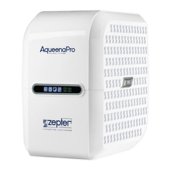
Page 7: Product Overview
AqueenaPro WT-100 Installation and Repair manual 5. Product overview 5.1. Water Purifier: Product Definition AqueenaPro WT-100 is reverse osmosis water purifier uses the semi-permeable membrane with pores small as 0.0001 micron. 5.2. Water flow principle First stage: 5-micron PP filter (WT-100-72) The PP filter has a 5 micron pore size that can effectively filter larger particles in water as rust, sand, and other solid impurities. -
Page 8: Technical Characteristic
Auto-flushing system Electric Shock Protection Type Type II 9.5 l (usable capacity 6l) Tank Capacity 2.5Gallons (usable capacity 1.6G) Suitable Water Quality Primly designed for municipal tap water. Rev. A Installation and Repair Manual AqueenaPro WT-100 Page 8 of 64... -
Page 9: Water Route Map
* at 3.5 bar feed water pressure and 25 C feed water temperature ** at 3.5 bar feed water pressure and 25 C feed water temperature; TDS < 750 ppm. Measured on closed tank. Rev. A Installation and Repair Manual AqueenaPro WT-100 Page 9 of 64... -
Page 10: Product Special Features
Automatic Control System: The system automatically controls the water auto flush process and control pure water production process, ( it stops water production if it is no inlet water or tank is full). Rev. A Installation and Repair Manual AqueenaPro WT-100 Page 10 of 64... -
Page 11: Product Overview
AqueenaPro WT-100 Installation and Repair manual 5.8. Product overview Rev. A Installation and Repair Manual AqueenaPro WT-100 Page 11 of 64... -
Page 12: Repair Information
To secure and keep appropriate repair and maintenance level, sales representative must fill section “Service Contact”. The customer should have easy access to professional ZEPTER service. Rev. A Installation and Repair Manual AqueenaPro WT-100 Page 12 of 64... -
Page 13: Note For Zct Users
Note: If the serial number being recorded, use only numbers (without “letters” only digits 001403180001) Lot number format: PL02 (nnnn-Wnn) – mandatory information Warranty type Invoice date Correct spare part(s) code Adequate failure code(s) and resolution code(s) Rev. A Installation and Repair Manual AqueenaPro WT-100 Page 13 of 64... -
Page 14: Product Installation
It is preferable to install the AqueenaPro near a sink so that inlet and reject water lines are easily available. Avoid sharp bends in the pipe. Do not bend or block the rejected water tube. Do not confine the AqueenaPro in a tight cabinet. Rev. A Installation and Repair Manual AqueenaPro WT-100 Page 14 of 64... -
Page 15: Recommended Tools For Installation
All external and internal water connections are done using flexible tubing and quick connect fittings. As an additional safety features all connections are secured with safety locking clips that make it impossible to accidentally remove any tubing. Locking clip Quick connectors Collet Rev. A Installation and Repair Manual AqueenaPro WT-100 Page 15 of 64... -
Page 16: Tube Connection
Secure it by locking clip. To disconnect the tube from the quick connector follow next steps: Remove the locking clip Slightly pull out the collet Pull the tube out Rev. A Installation and Repair Manual AqueenaPro WT-100 Page 16 of 64... -
Page 17: Inlet Water Tube Installation
Standard accessories 1/2` inline feed water connector 1/2` inline feed water connector with applied reduction 3/4` Note! Teflon tape must be applied to all connections. Rev. A Installation and Repair Manual AqueenaPro WT-100 Page 17 of 64... - Page 18 Connect white tube to the feed water connector. Unscrew the nut from the connector, put it on the white tube, connect the tube and secure it by the nut. Rev. A Installation and Repair Manual AqueenaPro WT-100 Page 18 of 64...
-
Page 19: Waste Water Pipe Installation
Drill 7 mm hole in the drain pipe under the sink. 3. Connect the white tube in to upper part of the clamp and tighten it with the nut. Rev. A Installation and Repair Manual AqueenaPro WT-100 Page 19 of 64... - Page 20 Ensure that tube is inserted correctly in to pipe (see pictures below), assembly the clamp to the pipe and secure it with screws. Connect the tube in to CONC. WATER connector. Rev. A Installation and Repair Manual AqueenaPro WT-100 Page 20 of 64...
-
Page 21: Pure Water Faucet Installation
Remove the pure water faucet from the accessories bag. Unscrew washers from the faucet. Place the faucet in to its position and secure by nuts from the bottom of the sink. Do not forget apply the washers on the Rev. A Installation and Repair Manual AqueenaPro WT-100 Page 21 of 64... -
Page 22: Main Unit Installation
The first two tanks can contain black residues. It is carbon particles washing away from the carbon filter. It will not affect future system performance or quality of purified water. Rev. A Installation and Repair Manual AqueenaPro WT-100 Page 22 of 64... -
Page 23: Ro Membrane Installation
Open the main unit – remove the top cover. Pease refer to chapter 13 How to open AqueenaPro. Remove the locking clip from quick connector and unplug the tube from the RO membrane housing. Locking clip Rev. A Installation and Repair Manual AqueenaPro WT-100 Page 23 of 64... - Page 24 Damages caused by forced installation are not covered under the warranty. Pay attention to direction how the membrane is installed. Verify, before installation, if the membrane has O-ring. Rev. A Installation and Repair Manual AqueenaPro WT-100 Page 24 of 64...
- Page 25 Checks if the sealing was not loosen and if it is correctly mounted, before the RO housing is closed. The sealing must be put on therear od the shell. Close the unit. Note: Verify all connections before the top cover is put back – no water leakage. Rev. A Installation and Repair Manual AqueenaPro WT-100 Page 25 of 64...
-
Page 26: Maintenance And Filter Replacement Method
- the filter life time will be exceeded soon. Red light along with the audible alarm (4 times buzz) and the filter must be exchanged immediately. Further use of the filter is not recommended. Rev. A Installation and Repair Manual AqueenaPro WT-100 Page 26 of 64... -
Page 27: Ro Membrane Replacement Time
WT-100-15 RO membrane The manufacturer recommends changing the RO membrane WT-100-15 with the Coconut filter; therefore referring to Coconut filter replacement period according Filter Status Display (No. 5) Rev. A Installation and Repair Manual AqueenaPro WT-100 Page 27 of 64... -
Page 28: The Filters Replacement Procedure
Coconut filter WT-100-75 is two way water flow filter and actual water flow depends on working stage of the unit, therefore it is important to follow the arrow on the label. Rev. A Installation and Repair Manual AqueenaPro WT-100 Page 28 of 64... - Page 29 Disconnect PP filter 5 m WT-100-72 3 filters set Change requested filter(s), connect tubes in to quick connectors and assemble set back on its position. Connect tubes to PP filter 5 m WT-100-72. Rev. A Installation and Repair Manual AqueenaPro WT-100 Page 29 of 64...
-
Page 30: After Filter Replacement
“Reset” button: Select the corresponding filter and press the “reset” button, hold for more than 3 seconds until it is effective. After resetting, the red light will turn green. Rev. A Installation and Repair Manual AqueenaPro WT-100 Page 30 of 64... -
Page 31: The Ro Membrane Replacement Procedure
Replace the filter – Pay attention to correct water flow! Check all connections and verify that no water leakage. Close the top cover. Open the inlet water valve and switch on the power supply. Rev. A Installation and Repair Manual AqueenaPro WT-100 Page 31 of 64... -
Page 32: Trouble Shooting Guideline
After the machine Non return valve has lost pressure Replace the non return valve is filled with High-pressure switch failure Replace the high pressure switch Rev. A Installation and Repair Manual AqueenaPro WT-100 Page 32 of 64... -
Page 33: Tools
High pressure pump pressure is not Measure the high pressure pump enough water pressure, replace if needed 11. Tools Flathead screwdriver 3x75 Philips screwdriver PH2 Allen key CH17,19 Pliers Rev. A Installation and Repair Manual AqueenaPro WT-100 Page 33 of 64... -
Page 34: How To Open Aqueenapro
PP 5 m Filter Coconut filter WT-100-72 WT-100-75 RO membrane housing Pellet carbon filter WT-100-16 WT-100-73 Remember! Grey connector – water flow in White connector – water flow out Rev. A Installation and Repair Manual AqueenaPro WT-100 Page 34 of 64... -
Page 35: Locking Plate Left And Right
Spare part: WT-100-86 Lock Right KIT (47+48+49+70) WT-100-87 Lock Left KIT (52+51+49+50+70) WT-100-69Tapping screw M3x12 with washer Ø3 Unscrew two screws WT-100-69 Release the locking plate and exchange to new one Rev. A Installation and Repair Manual AqueenaPro WT-100 Page 35 of 64... -
Page 36: Inlet Solenoid Valve (33)
Pay attention to correct locking plate. Left and right are not same! Self holding locking element The locking element with the spring WT-100-87 WT-100-86 14. Inlet solenoid valve (33) Tools: Philips screwdriver PH2 Rev. A Installation and Repair Manual AqueenaPro WT-100 Page 36 of 64... - Page 37 Installation and Repair manual Spare part: WT-100-79 Inlet solenoid valve kit Remove the top cover (WT-100-01) Position of inlet solenoid valve (33) – pump side Unscrew two screws Rev. A Installation and Repair Manual AqueenaPro WT-100 Page 37 of 64...
- Page 38 Only Solenoid valve kit WT-100-79 is possible to order. To install the inlet solenoid valve back follow the steps in reverse order. Note! Pay attention to correct position of solenoid valve and correct water flow. Rev. A Installation and Repair Manual AqueenaPro WT-100 Page 38 of 64...
-
Page 39: Low Pressure Switch (22)
15. Low pressure switch (22) Tools: Philips screwdriver PH2 Spare part: WT-100-81 Low Pressure Switch kit Remove the top cover (WT-100-01) Position of low pressure switch (22) – pump side Rev. A Installation and Repair Manual AqueenaPro WT-100 Page 39 of 64... - Page 40 Only Low Pressure Switch Kit WT-100-81 is possible to order. Set contain low pressure (22) switch and connect (21) Connect the white tube and two yellow wires back. Note! Pay attention to correct connection Rev. A Installation and Repair Manual AqueenaPro WT-100 Page 40 of 64...
-
Page 41: Display (55)
Dismount 2 screws (WT-100-69) and release the display box. Slightly pull the box out. Open the display box (WT-100-82; WT-100-54). ATTENTION! Use ESD protection when touching the PCB! Rev. A Installation and Repair Manual AqueenaPro WT-100 Page 41 of 64... - Page 42 Disconnect the flat cable from the connector. Release the PCBA board (WT-100-55) by removing two screws WT-100-70 Exchange the display board WT-100-55. To assembly the display box back follow the steps in reverse order. Rev. A Installation and Repair Manual AqueenaPro WT-100 Page 42 of 64...
-
Page 43: Control Board (24)
Spare part: WT-100-24 Computer control box with PCBA WT-100-23 Lower cover of control board WT-100-65 Cross recessed screw M3x8 To reach the control box , release the inlet solenoid valve (33) firstly. Rev. A Installation and Repair Manual AqueenaPro WT-100 Page 43 of 64... - Page 44 Do not lose lower cover (23) Remove the cable set from the connector Disassembly the PCBA from the box by releasing of two screws ATTENTION! Use ESD protection when touching the PCB! Rev. A Installation and Repair Manual AqueenaPro WT-100 Page 44 of 64...
- Page 45 Place the PCBA in to the box. Pay attention to correct position – side with components should be palce inside of the box. Put lower cover (23) and assemble the control box (23+24) on its position. Rev. A Installation and Repair Manual AqueenaPro WT-100 Page 45 of 64...
-
Page 46: Flashing Solenoid Valve (32)
10. Assembly the inlet solenoid valve (33) back, follow the steps in reverse order. Flashing solenoid valve (32) Tools: Philips screwdriver PH2 Spare part: WT-100-80 Flashing Solenoid Valve KIT Rev. A Installation and Repair Manual AqueenaPro WT-100 Page 46 of 64... - Page 47 Back side Front side High pressure switch Flashing solenoid valve WT-100-28 WT-100-32 Remove two screws (WT-100-65) Unplug water pipes from the quick connectors, disconnect white wires from the valve. Rev. A Installation and Repair Manual AqueenaPro WT-100 Page 47 of 64...
- Page 48 Grey connector connected to outlet connector (WT- to RO membrane 100-43) – concentr. water Note! Do not forget apply locking clips to quick connectors! Place outlet connect to its position Rev. A Installation and Repair Manual AqueenaPro WT-100 Page 48 of 64...
-
Page 49: High Pressure Switch (28)
Spare part: WT-100-83 High pressure switch KIT Back side Front side High pressure switch Flashing solenoid valve WT-100-28 WT-100-32 Release water pipe from the plastic screw cup WT-100-29. Rev. A Installation and Repair Manual AqueenaPro WT-100 Page 49 of 64... - Page 50 Only high pressure switch KIT WT-100-83 can be ordered. Pay attention to correct position of the flashing solenoid valve. To assembly the high pressure switch back follow steps in reverse order. Rev. A Installation and Repair Manual AqueenaPro WT-100 Page 50 of 64...
-
Page 51: Water Tank (40)
WT-100-36 Anchor ear WT-100-35 Spongy pads of anchor ear WT-100-68 Tapping screw M4x10 (8 pcs) WT-100-85 Tank Connector KIT (37+38+39) Remove the whole filter platform – 4screws from each side. Rev. A Installation and Repair Manual AqueenaPro WT-100 Page 51 of 64... - Page 52 Disconnect pipe from tank valve (41) Pull out outlet connectors (43) – all three. Remove the filter platform and put it aside. Note! Pay attention to cable set – do not pull. Rev. A Installation and Repair Manual AqueenaPro WT-100 Page 52 of 64...
-
Page 53: Leakage Sensor (59)
Follow the steps in reverse order to assembly the water tank (40) back. Do not forgot apply the locking clip to quick connector(s). 21. Leakage sensor (59) Tools: Philips screwdriver PH2 Spare part: WT-100-59 Leakage sensor WT-100-66 Tapping screw M3x10 Rev. A Installation and Repair Manual AqueenaPro WT-100 Page 53 of 64... - Page 54 Connect new leakage sensor to control board and assembly it back to its position. Place the leakage sensor (59) on the bottom of the device and secure with the screws. To close the device, follow the steps in reverse order. Rev. A Installation and Repair Manual AqueenaPro WT-100 Page 54 of 64...
-
Page 55: Pump (25)
22. Pump (25) Tools: Philips screwdriver PH2 Pliers Spare part: WT-100-78 Pump Kit Remove the whole filter platform – 4screws from each side. Disconnect pipe from tank valve (41) Rev. A Installation and Repair Manual AqueenaPro WT-100 Page 55 of 64... - Page 56 Pull out outlet connectors (43) – all three. Remove the filter platform and put it aside. Note! Pay attention to cable set – do not pull. Unplug the water pipes from the pump (25) Rev. A Installation and Repair Manual AqueenaPro WT-100 Page 56 of 64...
- Page 57 Installation and Repair manual Remove 3-set filter for better access to screws (64 + 27) and unscrew them. Remove the pump (25). Disconnect the red and black cable. Rev. A Installation and Repair Manual AqueenaPro WT-100 Page 57 of 64...
- Page 58 To assemble the new pump back follows the steps in reverse order. When water pipes are connected pay attention to correct water flow. Remember! Grey connector – water flow in White connector – water flow out Rev. A Installation and Repair Manual AqueenaPro WT-100 Page 58 of 64...
-
Page 59: Power Cord Extension (44)
23. Power cord extension (44) Tools: Philips screwdriver PH2 Spare part: WT-100-44 1.5A patch cord Release the bracket (45) for better manipulation, unscrew two screws (WT-100-69) Rev. A Installation and Repair Manual AqueenaPro WT-100 Page 59 of 64... - Page 60 Pull the cord (44) from the bracket (45) and exchange it. ATTENTION! To connect the wires back, pay attention to correct pair grey+red, brown + black . Use clamps as protection. Rev. A Installation and Repair Manual AqueenaPro WT-100 Page 60 of 64...
-
Page 61: Colour Cable Set
AqueenaPro WT-100 Installation and Repair manual 24. Colour cable set Unplug cables set from the control board connector (24). Disconnect 2 orange wires from inlet solenoid valve (33). Rev. A Installation and Repair Manual AqueenaPro WT-100 Page 61 of 64... -
Page 62: Aqueenapro Wt
Installation and Repair manual Disconnect 2 yellow wires from low pressure switch (22) Disconnect 2 white wires from inlet flashing valve (32). Disconnect 2 blue wires from high pressure switch (28). Rev. A Installation and Repair Manual AqueenaPro WT-100 Page 62 of 64... - Page 63 Exchange the colour wire set to new one. Connect all elements back Control board Inlet solenoid valve (33) - orange Low pressure switch (22) – yellow Flashing valve (32) – white Rev. A Installation and Repair Manual AqueenaPro WT-100 Page 63 of 64...
- Page 64 AqueenaPro WT-100 Installation and Repair manual High pressure switch (28) – blue Pump (25) - red+ green, black + brown Power cord (44) - grey+red, brown + black Rev. A Installation and Repair Manual AqueenaPro WT-100 Page 64 of 64...
Need help?
Do you have a question about the AqueenaPro WT-100 and is the answer not in the manual?
Questions and answers
заменил 5 фильтров, при подключении горят красным 4 поля, через 5 сек. насос перестаёт работать и система истошно вопит.
If all four lights are red and blinking, and the pump stops working on the Zepter AqueenaPro WT-100 after replacing five filters, it indicates a water leakage. The system detects the leakage and responds by flashing all status icons (“Operation,” “Water source,” “Standby,” and “Flush”) along with a sound alarm, and the pump stops as a safety measure.
This answer is automatically generated
После года пользования на выходе получается 1л. чистой воды.