Advertisement
Quick Links
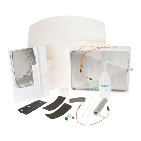
MONOGRAM FREEZER ICING KIT WR49X10021
DISCONNECT POWER BEFORE SERVICING TO PREVENT
ELECTRICAL SHOCK HAZARD
Parts Included:
522-08F
Drain pan assembly with ground wire
squeeze bottle
522-08E
Bar of PermaGum
522-08G
Insulating styrofoam piece
for side wall
Prepare Freezer Compartment
1.
Lift to remove top grille panel frame. Set aside. Locate
and disconnect or cut the 2 drain tube clamps in the
compressor compartment.
EVAPORATOR
COMPARTMENT
DRAIN
TUBE
522-08L
DRAIN TUBE CLAMPS (2)
2.
Remove ice bucket, icemaker, shelves and all materials
in the freezer compartment.
Installation Instructions
INSTALLATION INSTRUCTIONS
250ml
522-08D
522-08Y
Orange jumper Wire, with female
bullet connector on one end and
stack terminal on opposite end (not
required on models produced after
10/94).
DIVIDER
COMPRESSOR
COMPRESSOR
DRAIN PAN
IMPORTANT: Follow these instructions completely. Procedure
will vary slightly for non-dispenser models.
LEFT
2 Wire ties
Insulation pieces to cover entire
evaporator compartment
522-08J
3.
Remove the rear
panel section
(plenum). Discon-
nect the wiring to
the light socket
and over-tempera-
ture thermostat if
present.
Page 1 of 4
BACK
TOP
NOTCH
FRONT
EVAP ORIFICE
PERF
LINE
522-08H
Plastic "Xmas Plug" ratchet
fastener (not required on models
produced after 10/94).
Ple num
522-08W
RIGHT
EVAPORATOR
PLATE
INSULATION
REAR
FRONT
TOP
Disconnect
Light and
Thermostat
70836-00
Advertisement

Related Manuals for GE WR49X10021


Summary of Contents for GE WR49X10021
-
Page 1: Installation Instructions
MONOGRAM FREEZER ICING KIT WR49X10021 INSTALLATION INSTRUCTIONS IMPORTANT: Follow these instructions completely. Procedure DISCONNECT POWER BEFORE SERVICING TO PREVENT will vary slightly for non-dispenser models. ELECTRICAL SHOCK HAZARD Parts Included: BACK LEFT RIGHT 522-08F NOTCH Drain pan assembly with ground wire... - Page 2 Remove the evaporator fan/motor bracket assembly. Remove fan support panel. Fan Support Panel 522-08V Evaporator Fan/Motor Bracket Disconnect the drain pan heater leads. Remove drain pan/heater assembly by pulling drain tube through the freezer side wall. Discard entire assembly. Pull off the styrofoam pieces on the right wall and front right corner.
- Page 3 Push drain pan assembly up and against the bottom of Press insulation pieces onto the top and front side the evaporator. The bottom of the styrofoam drain pan plates on the left side of the evaporator. Press must be evenly aligned with the bottom of the insulating insulation piece on rear plate (if not present).
- Page 4 Install insulation piece on the back side of the evapora- Reinstall freezer rear panel (plenum) and icemaker. tor fan support (trim on dotted line for 36" or 42" Check to be sure icemaker fill tube is positioned models). Reinstall the panel. correctly over the fill cup.