
Subscribe to Our Youtube Channel
Related Manuals for Midea MTE150-P2004S


Summary of Contents for Midea MTE150-P2004S
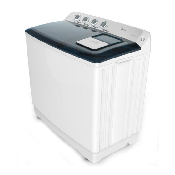
- Page 1 Service Manual TWIN TUB WASHING MACHINE Model:MTE150-P2004S Note: Before serving the unit, please read this at first, Always contact with your service center if meet problem.
-
Page 2: Table Of Contents
CONTENTS 1. PRECAUTION............1-1. -
Page 3: Precaution
1. PRECAUTION When performing troubleshooting and part replacement during servicing, note the following safety precautions: 1-1. Safety Precautions 1-1-1. Use Genuine Parts The components of the washing machine have safety features such as non-combustibility and voltage withstanding. Therefore, always use the same part as suggested by the maker. In particular, be sure to use only designated parts in case of major safety parts identified by the marker. -
Page 4: Caution For Safety
2. CAUTIONS FOR SAFETY • Please observe the following notes for safety. • The symbols indicate as follows. Symbol Meaning Indicates possibility of death or serious injury of a repair technician and a person nearby through the misconducted work, or of a user by a defect of the WARNING product after the work performed by the technician. - Page 5 2. CAUTIONS FOR SAFETY WARNING • After repair, measure insulation resistance between the charging part (power cord plug) and the non-charging metallic part (ground) with an insulation resistance meter (500V). The resistance shall be 10M• or more. CHECK INSULATION Failing to check the insulation resistance may cause a short circuit, electric RESISTANCE shock or other diseases to the customer.
- Page 6 2. CAUTIONS FOR SAFETY WARNING • Do not put inflammable into the washing tub. Do not put cloths stained with kerosene, gasoline, benzene, thinner, alcohol, etc. lt may cause a fire or explosion. AVOID INFLAMMABLE • Do not touch the laundry before the spin basket stops completely. The laundry entangles your hand causing an injury even if the basket rotates DO NOT TOUCH slowly.
-
Page 7: Description Of Parts
3. DESCRIPTION OF PARTS... -
Page 8: Control Panel
3. DESCRIPTION OF PARTS 3-1. Control Panel ● Water inlet: be used to inject water. ● Wash timer: be used to select required washing time. ● Spin timer: be used to select required spinning time. ● Wash selector: Choose “ Normal”or“ Heavy” according to laundry fabric. ●... -
Page 9: Installation
3. DESCRIPTION OF PARTS 3-2. Installation 3-2-1. Level Specifications and Wall - Clearance Distances 1) Install the washing machine on a solid and level floor. 2) Place the machine at least 15cm away from the wall. 3) Placement on an inclined, weak or rough floor may cause abnormal noise or trembling. -
Page 10: Grounding
3. DESCRIPTION OF PARTS 3-2-3. Grounding 1) Upon installing grounding,make sure if power socket is out of power outlet. 2) Grounding should be connected to eithermetal water supply pipe or copper grounding pole deeper than 25cm in the damp ground. (Fig 1) 3) If water pipe is a plastic, no protection is obtained from a possible electric shock. -
Page 11: Disassembly And Teassembly
4. DISASSEMBLY AND REASSEMBLY ITEM HOW TO DISASSEMBLE AND ASSEMBLE PICTURE TIMER- 1. Unscrew the screw of the plusator. (Fig (Fig 1) WASHING AND TIMER- SPINNING 2. Pull off the knobs by the screwdriver which with"-"Sharp. (Fig 2) (Fig 2) 3. - Page 12 4. DISASSEMBLY AND REASSEMBLY ITEM HOW TO DISASSEMBLE AND ASSEMBLE PICTURE BASKETSPINNI (Fig 1) 1. Unscrew the screws (Red circle part) from the back of model by screwdriver. (Fig 1) 2. Unscrew the screws of the handle by (Fig 2) screwdriver.
- Page 13 4. DISASSEMBLY AND REASSEMBLY ITEM HOW TO DISASSEMBLE AND ASSEMBLE PICTURE BASKETSPINNI (Fig 6) 6. Pull off the breaking belt and drain belt(Red circle part). (Fig 6) (Fig 7) 7. Unscrew the screw at the joint of spin M8 Box driver tub &...
- Page 14 4. DISASSEMBLY AND REASSEMBLY ITEM HOW TO DISASSEMBLE AND ASSEMBLE PICTURE ASSY GEAR (Fig 1) 1. Unscrew the screw of the plusator. (Fig 1) (Fig 2) 2. Take out the plusator's plate, (Fig 2) (Fig 3) 3. Pull off the axle of spin tub & screw of breaking plate, (Fig 3) Further step check (Fig 6) (Fig 4)
- Page 15 4. DISASSEMBLY AND REASSEMBLY ITEM HOW TO DISASSEMBLE AND ASSEMBLE PICTURE (Fig 1) MOTOR- 1. Unscrew the screw of the plusator. SPINNING (Fig 1) & MOTOR- WASHING 2. Take out the plusator's plate, (Fig 2) (Fig 2) (Fig 3) 3. Pull off the axle of spin tub & screw of breaking plate, (Fig 3) Further step check (Fig 6) 4.
- Page 16 4. DISASSEMBLY AND REASSEMBLY ITEM HOW TO DISASSEMBLE AND ASSEMBLE PICTURE (Fig 1) MOTOR- 5. Remove the plastic bag on the SPINNING connection part, & &detach end connector of motor MOTOR- wires(Fig 1) WASHING (Fig 2) 6. Unscrew the 3 screws of Spin motor(Red circle part).
- Page 17 4. DISASSEMBLY AND REASSEMBLY ITEM HOW TO DISASSEMBLE AND ASSEMBLE PICTURE (Fig 1) MOTOR- 1. Follow same as disassembling SPINNING sequence of the & Motor-Spinning, (1) through (2) MOTOR- WASHING 2. Unscrew pulley-Motor nut to disassembled the pulley(Fig 1) (Used M8 Spinner / open spinner) 3.
- Page 18 4. DISASSEMBLY AND REASSEMBLY ITEM HOW TO DISASSEMBLE AND ASSEMBLE PICTURE (Fig 1) MOTOR- 1. Follow same as disassembling SPINNING sequence of the & Motor-Spinning, (1) through (2) MOTOR- WASHING 2. Unscrew pulley-Motor nut to disassembled the pulley(Fig 1) (Used M8 Spinner / open spinner) 3.
- Page 19 4. DISASSEMBLY AND REASSEMBLY ITEM HOW TO DISASSEMBLE AND ASSEMBLE PICTURE (Fig 1) COVER-TOP 1. Open the spin lid,install the tub frame. (Fig 1) 2. Install the frame and control panel (Fig 2) rightly . (Fig 2) FILTER O.F G) &...
-
Page 20: Schematic Diagram
5. SCHEMATIC DIAGRAM 5-1 SINGLE VOLTAGE... -
Page 21: Trouble Shooting
6. TROUBLE SHOOTING TYPICAL FAILURE POSSIBLE CAUSE REPAIR Spinning Brake shoe is worn off or broken Replace brake basket does shoe not stop Brake arm does not move Replace brake frame Brake spring is broken away or Replace brake elasticity is insufficient spring Excessive Machine is not level. -
Page 22: Check Point After Repair
7. CHECK POINT AFTER REPAIR After repairing, be sure to make the following trial operation to see if the washer operates normally. Check Point Inspection & Judgement 1) Insulation resistance Unplug the cord from the power outlet and turn on all the timers. Then measure the insulation resistance between the plug (both of 2 pins) and grounding wire of the machine.
Need help?
Do you have a question about the MTE150-P2004S and is the answer not in the manual?
Questions and answers