Table of Contents
Advertisement
Quick Links
Advertisement
Table of Contents

Summary of Contents for Stagemaker SR
- Page 1 Technical guide www.stagemaker.com...
-
Page 2: Table Of Contents
Gear ..................................35 LIST OF MATERIALS AND COATINGS ........................36 STAGEMAKER PRODUCT CODE EXAMPLE ......................37 LOAD RANGE AND DUTY CLASSES ........................38 Hoist classifications .............................. 38 STAGEMAKER RANGE OF FLIGHT CASE ........................ 40 STAGEMAKER RADIO LOAD CELL SYSTEM ......................45 04/2014... - Page 3 TECH N ICAL GUIDE 4/55 04/2014...
-
Page 4: Update History
TECH N ICAL GUIDE 5/55 UPDATE HISTORY Section Changes Date Handled by First draft version 10/2012 ISOTAPA First correction round 12/2012 ISOTAPA 2.8, 3.1.1, 3.2.1 Separate versions for SI 50 Hz / SI 60 Hz / IMP 60 Hz created 12/2012 ISOTAPA Hoist configuration... -
Page 5: General
GENERAL General description STAGEMAKER® hoists for showbusiness are electric chain hoists that are designed to handle stage and theatrical equipment and enable the safe and accurate positioning of speakers, lighting systems, stage sets, sceneries, etc. STAGEMAKER® hoist‟s features and options, compact design and on-going adaptability (R&D, close corporation with the entertainment industry) make this system the best choice for your stage productions. -
Page 6: Normal Position
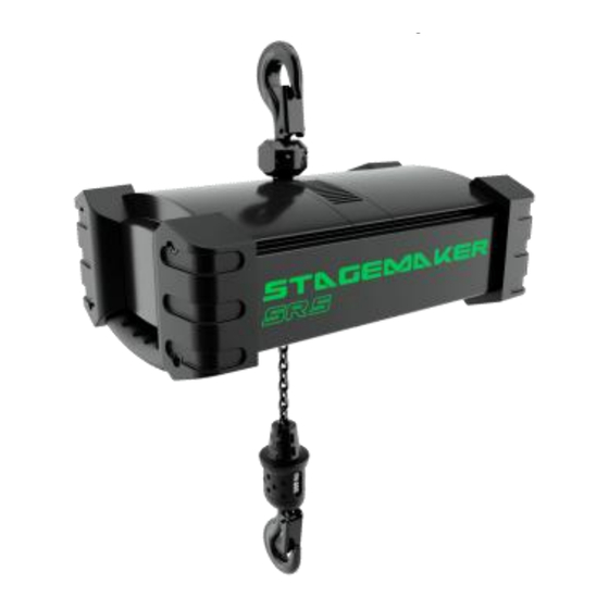
TECH N ICAL GUIDE 7/55 Identifying the key parts of the hoist Pos. Part Description Hoisting machinery Equipment composed of hoist frame, hoisting motor, gear, clutch and brake Upper hook Fixed suspension, normally used when hoist is operated in normal position Upper hook Rotating upper hook, normally used when hoist is operated in inverted position Lower Hook block... -
Page 7: Standard Features
TECH N ICAL GUIDE 8/55 Standard features Mechanics Single fall up to 500 kg D8 as standard, BGV-D8+ ready New “Perfect Push”, patented concept, 5 pocket load wheel, fitted with 5 intermediate teeth. This innovation provides improved chain guiding and chain flow, to help reduce the risk of chain jamming. ... - Page 8 TECH N ICAL GUIDE 9/55 Electrics Single speed motors either 1500 rpm or 3000 rpm The Limitflux is a built-in limit switch device in the CHAINFlux MKII® that‟s allow to control setting of hoist or hook position in industrial suspension or climbing configuration (on version B only). ...
-
Page 9: Optional Features
TECH N ICAL GUIDE 10/55 Optional features Mechanics BGV-D8+ ready (static safety factor 10) Manual brake release Upper suspension fixed eye Hook block with safety load hook, self locking Lockable rotation of hook forging Soft rain cover. -
Page 10: Product Range
TECH N ICAL GUIDE 11/55 Product range S.W.L. Motor Hoisting Frame Duty group Chain Gear life Max. temp power Falls Motor type speed ED% Starts/hour size size [°C] [m/min] [kg] [kW] 4 x 11 1600 MT07CA200 0.23 4 x 11 MT07CA104 0.45 5 x 14... -
Page 11: Main Components
TECH N ICAL GUIDE 12/55 MAIN COMPONENTS Motor 3.1.1 Hoisting motors The hoisting motor is specially designed for hoisting purposes with good efficiency. The motor has an aluminum frame with cooling ribs for efficient cooling. Power Speed 230 V – Amps 380–415 V –... -
Page 12: Gear
49.894 SR 5 3-step 49.894 SR 5 3-step 25.286 SR 10 3-step 71.777 SR 10 3-step 71.777 SR 10 3-step 35.832 3.2.2 AGMA rating Hoisting gears for SR 2-SR 5 are AGMA class 10 (AGMA 390.03 and AGMA 2000-A88). 04/2014... -
Page 13: Electrics
TECH N ICAL GUIDE 14/55 Electrics 3.3.1 Cable inputs Pos. Part Free cable gland Power supply Control cable * NOTE: Accepted outside diameters (O.D.) of the cable are: 15.9 mm – 19.0 mm. 04/2014... -
Page 14: Wiring Principle - Configuration A
TECH N ICAL GUIDE 15/55 3.3.2 Wiring principle – Configuration A Pos. Part Hoisting motor Main brake Auxiliary brake Direct control voltage board Power supply Pendant* or controller (option) *Not available in North America for direct control hoist. 04/2014... -
Page 15: Wiring Principle - Configuration B
TECH N ICAL GUIDE 16/55 3.3.3 Wiring principle – Configuration B Pos. Part Hoisting motor Thermal sensor Main brake Auxiliary brake Limit switches Control plug Power plug Power supply Pendant or controller (option) 04/2014... -
Page 16: Hoisting Brakes
TECH N ICAL GUIDE 17/55 Hoisting brakes The chain hoist is equipped with a disc brake. There is one rotating disc with two lining surfaces. The brake coil is energized by DC voltage coming from brake rectifier. The brake rectifier converts AC voltage into DC voltage. The protection class is IP66. -
Page 17: Double Brake
TECH N ICAL GUIDE 18/55 3.4.1 Double brake The main brake and auxiliary brake are assembled on the same hub. When the hoisting motion is required, the service brake and the auxiliary brake are energized simultaneously from the brake board. When the hoisting motion is stopped, the service brake is switched off immediately while the auxiliary brake stays energized for a few milliseconds by the motor inductive effect. -
Page 18: Brake Coil Voltages And Resistance
All values are also considered as +/-10% of nominal voltage. Brake coil resistance Brake torque Coil resistance Frame size Brake type Rated voltage [V] [Nm] [lbf] min. [Ohm] max. [Ohm] SR 2 BFK457-06 2.063 496.6 564.9 SR 2 BFK457-06 2.063 1661 1949 SR 5 BFK457-06 5.012... -
Page 19: Overload Device: Slipping Clutch
TECH N ICAL GUIDE 20/55 Overload device: Slipping clutch The overload protection of the unit is ensured through a direct acting limiter of slipping clutch type. This device is according to EN14492-2 requirements for such units. It is set in such a way that it allows the unit to lift a load corresponding to the dynamic test load (110% – 125% of SWL) and prevents the unit from lifting a load of 160% of SWL. -
Page 20: Limit Switch
TECH N ICAL GUIDE 21/55 Limit switch (on B version) 3.6.1 Micro switch operated limit switch with industrial chain guide (Std) The lifting hook’s maximum up and down positions are secured by the electric limit switch located under the chain guidance system. The switches are activated alternately by the lifting hook’s upper cone and the slack fall stop. - Page 21 TECH N ICAL GUIDE 22/55 3.6.2 LimitFlux : magnetic operated limit switch with Chainflux (Std) PRINCIPLES > The Limitflux is a built-in limit switch device in the CHAINFlux MKII® that’s allow to control setting of hoist or hook position in industrial suspension or climbing configuration. >...
- Page 22 TECH N ICAL GUIDE 23/55 DIMENSIONS The rings size is the same for all hoists, whatever their size. The only difference is the chain path. Diameter = 64 mm Height = 38 mm SR10 Ring assembly SR5 Ring assembly POSITIONNING THE LOWER LIMIT SWITCH RING So that the setting ring can leave the chain bucket without any constraint, the ring must not be too close from the slack fall stop.
-
Page 23: Rotating Limit Switch (Option)
TECH N ICAL GUIDE 24/55 3.6.3 Rotating limit switch (option) Pos. Part Fixing plate Coupling Rotating limit switch, 2-step 04/2014... -
Page 24: Functional Description Of The Limit Switch
Two (2) cams are not connected to the controls, and can thus be freely used for end user requirements. The operation limits for standard rotating L/S are as follows: HOL [m] max. Frame size Chain Speed [m/min] Ratio 180 Ratio 280 SR 2 4x11 SR 2 4x11 SR 5 5x14 SR 5 5x14... -
Page 25: Chain Reeving Components
TECH N ICAL GUIDE 26/55 Chain reeving components 3.7.1 Chain drive (PerfectPush) The chain hoist units are fitted with a special patented chain drive which includes additional supporting teeth on the sprocket. Those teeth improve the support of the chain and therefore reduce the stresses and the wear. The chain sprocket has five pockets and five intermediate teeth. -
Page 26: Chain Sprocket
TECH N ICAL GUIDE 27/55 3.7.2 Chain sprocket Frame size Chain sprocket Chain Nbr. of pockets D prim [mm] D axe [mm] [H7] B [mm] SR 2 SINGLE 4x11 35.87 16.4 SR 5 SINGLE 5x14 45.61 21.4 25.7 SR 10... -
Page 27: Suspension Hook
TECH N ICAL GUIDE 28/55 Suspension hook 3.8.1 Fixed suspension hook SR02 SR05/10 Dimensions [mm] Frame size Hook size SR 2 RSN012T 7.75 7.75 15.5 15.5 15.5 SR 5 RSN020T 8.2. SR 10 RSN08T 39.5 37.5 3.8.2 Rotating upper hook... -
Page 28: Hooks
29/55 Hooks Hooks are designed according to DIN15401. Material is 34 CrMo 4. Dimensions [mm] Marking/ Frame Reeving Hook size size class ØM Øa1 SR 2 012T RSN012T 10.5 SR 5 020T RSN020T 13.5 SR 10 RSN04V 14.5 SR 10 RSN08V 14.5... -
Page 29: Hook Blocks And Bottom Hook Blocks
3.9.1 Hook blocks and bottom hook blocks Single fall (1/1) Pos. Part Limit switch activator Grip area Turnable hook with safety latch, axial needle bearings Dimensions [mm] Frame size SR 2 SR 5 SR 10 1/1 SR 10 1/2 04/2014... -
Page 30: Hoisting Chains
3.10.1 Safety factors according to standards EN standard EN818-7 Frame size Static safety factor (grade 80) 3.10.2 Chains LABEL 11 t Dimensions SR 2 SR 5 SR 10 Chain size Unit 4 x 11 5 x 14 7 x 20 +0.2 +0.2... -
Page 31: Chain Bags
TECH N ICAL GUIDE 32/55 Safety Factor according chain grade 80/100 Hoist type Hoist type Speed Chain Safety Factor Safety Factor (kg) (m/min) Falls (mm) with grade 80 with grade 100 SR2 124 m2 A 4X11 16,38 SR2 128 m2 A 4X11 16,38 SR5 1216 m1 A... -
Page 32: Chain Loading Table
TECH N ICAL GUIDE 33/55 Chain bags Dimension [mm] Frame size Bag capacity [m] SR 2 SR 5 SR 5 SR 10 Textil material Polyester 1100 denier Fabric TER 630 Weight 630 g/m2 Breaking 230/210 daN/5 cm Tear 22/17 daN... -
Page 33: Pendant
Emergency Stop is a push-to-maintain, turn-to-release, red mushroom head button. Two push buttons for each motion, one for each direction of travel. Contacts for motion buttons are mechanically interlocked and momentary type. *Multiple control done by STAGEMAKER controller ( See STAGEMAKER controller Technical guide) 04/2014... -
Page 34: Lubrication
TECH N ICAL GUIDE 35/55 LUBRICATION Chain To extend chain lifetime, lubrication is recommended. Lubrication interval varies from month to one year depending on usage. Lubrication shall be done before signs of corrosion or dryness. Lubricate the chain with suitable lubrication. Lubricant for chain shall be water resistant, non-adhesive, transparent thin oil, which is able to penetrate. -
Page 35: List Of Materials And Coatings
TECH N ICAL GUIDE 36/55 LIST OF MATERIALS AND COATINGS MATERIALS: Part Fabrication Frame Pressure die casted aluminum alloy Covers Pressure die casted aluminum alloy Profiles Extruded aluminum alloy Gear wheels Alloy steel Chain bag TER 630 Lubricant Oil type Dexron III (gear) / Mobil Gear 632 (chain) Hooks Forged steel;... -
Page 36: Stagemaker Product Code Example
TECH N ICAL GUIDE 37/55 STAGEMAKER PRODUCT CODE EXAMPLE Feature Code Feature Available properties code Hoist type Stagemaker Frame size Frame size 125 kg 250 kg 500 kg SWL / 10 800 kg 1000 kg 1600 kg 2000 kg 50 Hz [m/min]... -
Page 37: Load Range And Duty Classes
TECH N ICAL GUIDE 38/55 LOAD RANGE AND DUTY CLASSES Hoist classifications The mechanism group – M4, M5 or M6 – of an electric chain hoist depends on operating time per working day and on the class of load spectrum. The hoist operating time (O ) can be calculated by using following formula: Actual load spectrum factor can be calculated using following table:... - Page 38 TECH N ICAL GUIDE 39/55 Class of load spectrums: L1 Light Mainly operated at very low loads and in exceptional cases at maximum loads. L2 Medium Operated continually at low loads and frequently at maximum loads. L3 Heavy Operated continually at medium loads and frequently at maximum loads.
-
Page 39: Stagemaker Range Of Flight Case
TECH N ICAL GUIDE 40/55 RANGE OF STAGEMAKER FLIGHT CASES Flight cases for hoist /definition PREMIUM VERSION • Configuration type "trunk" • Top hinge cover • Panel all Birch shot 9 mm finish hexa black ultra resistant • 2 fasteners recessed Butterfly •... - Page 40 TECH N ICAL GUIDE 41/55 ECO VERSION ● Configuration type "trunk" ● Cover top hinge ● Panel all Birch shot 9 mm ● 2 fasteners recessed Butterfly ● 2 stop cover ● 4 recessed spring-loaded handles ● 4 casters 2 locking on turntables D100 INSIDE DISPOSITION •...
- Page 41 TECH N ICAL GUIDE 42/55 BASE VERSION ● Type tray handling ● Panel all Birch black ● 2 handles pierced in the side posts ● stacking bins, 2 skates on top ● separate storage area for the chain Flight cases for controlers /definition PREMIUM VERSION ...
- Page 42 TECH N ICAL GUIDE 43/55 Flight cases range / dimensions PREMIUM VERSION Dimensions Designation (length x wide x height) Flight case for 2 x SR2 (simple or double brake) 910 x 575 x 540 Flight case for 2 x SR5 (simple or double brake) 1130 x 595 x 605 Flight case for 2 x SR10 (simple or double brake) 1200 x 630 x 655...
- Page 43 TECH N ICAL GUIDE 44/55 Flight cases stickers Sticker for Stagemaker type / quantity Production Sticker for Stagemaker flight cases 04/2014...
-
Page 44: Stagemaker Radio Load Cell System
TECH N ICAL GUIDE 45/55 STAGEMAKER RADIO LOAD CELL SYSTEM Why load monitoring on stage is so important? Tons of equipment above people: Hanging tons of sound and lighting equipment above spectators and performers is a serious matter, especially in light of the trend of ever increasing load weight and movement. - Page 45 > Fatigue rated load cells: All STAGEMAKER load cells are fatigue rated, an important feature especially for fixed and long-term installations. The load cell's ability to withstand successive load cycles for long periods of time without the risk of failure or damage to the steel, affords peace of mind for the user.
- Page 46 > Expandability: Easily expandable by simply adding more load cells to an existing system. > Multiple system integration: Different Stagemaker load cell users can combine their load cells into one system when necessary, and one large system can be split into several smaller systems. Both wired and wireless, load cells and various capacities and types (SRLI Hoist Integrated and SRLM with shackles) can be used together.
- Page 47 TECH N ICAL GUIDE 48/55 STAGEMAKER SR10 with shackles load cell STAGEMAKER SR10 with integrated load cell SRLM STAGEMAKER RADIO LOAD CELL SRLI STAGEMAKER RADIO LOAD CELL 04/2014...
- Page 48 TECH N ICAL GUIDE 49/55 SRLM Stagemaker radio load cell system / Description “Designed for quick instillation and versatile use” Technical specifications: R.F.: 2.4 GHz range – other ranges available. R.F. transmission range: Up to 450' /150m in normal operation conditions (outdoors line of sight).
- Page 49 Suitcase for storage and transportation of load cell (for 4 or 8 load cells) Set point, for integration of STAGEMAKER RADIO LOAD CELL SYSTEM system with any controller activates E-stop and/or audio visual alarm in case of overloads or underloads.
- Page 50 TECH N ICAL GUIDE 51/55 SRLI Stagemaker radio load cell system Description “ Low headroom– no shackles needed” Technical specifications: R.F.: 2.4 GHz range – other ranges available. R.F. transmission range: Up to 450' /150m in normal operation conditions (outdoors line of sight). Longer transmission ranges are optional.
- Page 51 Suitcase for storage and transportation of load cell (for 4 or 8 load cells) Set point, for integration of STAGEMAKER RADIO LOAD CELL SYSTEM system with any controller activates E-stop and/or audio visual alarm in case of overloads or underloads.
- Page 52 TECH N ICAL GUIDE 53/55 Stagemaker radio load cell system / Dimensions Load cell type Safety factor Resolution Shackle Size* Load Cell weight (max.) (max.) (max.) (max.) (min.) (kg) (kg) (kg) (mm) (mm) (mm) (mm) (mm) inch 5/8, 1/2 SRLM25 - SRLI25...
- Page 53 Stagemaker Central Radio Receiver SYSTEM REQUIREMENTS For Stagemaker radio load cell system optimal performance, the following are the minimum system requirements: PC or Laptop equipped with min. 256k cache, CD-ROM, USB 2.0 port, HD 40GB *, Windows (98 / Me / 2000 / XP/VISTA/Win7/Win8/Mac with Win emulator). Screen with resolution of 1024/768 ** * For using the REPORT feature (saving the data collected).
- Page 54 The output may be applied on activation of any kind of alarm/alerting light along the motor controller stop command. Using the Rigger and the Theatre family Stagemaker controller – there is an optional direct connection from the controller to the set point interface.
- Page 55 Distributors in Germany, Holland, Belgium, Italy, Argentina, Austria, Brazil, Chilli, Ireland, United Kingdom, Spain, Sweden, Norway, Finland, France, Portugal, Hungary, Poland, Russia, Denmark, China, Thailand, Indonesia, Malaysia, United States, Canada, Mexico, etc. To locate distributor in your country, please consult: www.stagemaker.com STAGEMAKER Europe VERLINDE 2, boulevard de l’Industrie - B.P.
Need help?
Do you have a question about the SR and is the answer not in the manual?
Questions and answers