Table of Contents
Advertisement
Quick Links
MS300
3-Circuit
Intercom
Master Station
Instructions
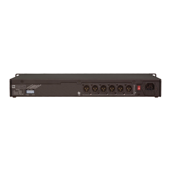
A. Connections:
AC:
Before attaching the IED power cable, check that the voltage setting is correct for your area
and that the fuse is the right value. (110/120V- 2A @250V; 220/240V - 1A@250V). Assure that
the front panel power switch is in the Off position. Connect the IED cable to the MS300 and
the power source. Switch the unit On at the Front panel. The top LED in the Status column
on the front should light - green. The three lower LEDs will also remain green unless there
is a problem on that circuit, in which case the LED will turn red.
There is room for a spare fuse in the IED inlet.
Comms circuits:
Your groups of stations should now be connected to the appropriate XLR jack, A, B or C.
If you have more cable runs than the number of XLR jacks for a particular circuit, you can
easily increase the available jacks with an SB1 Adaptor or with Y-cables. It is essential that
you check all your station interconnect cables for correct phasing. If Pin 1 is grounded
anywhere other than in the MS300 it will create a serious problem. The same is true with Pin
1/3 reversals which can easily happen when switching genders. Some mis-wiring will still
allow a cable to work with a microphone, but will render an intercom system useless.
Setting the DIP switches:
There are 8 switches in the DIP group. In the MS300 only 3 are active.
No's 5 thru 7 lift the 200W termination circuit from circuits A, B and C. The standard position
for this switch is Down, with the termination circuit connected. The most common of the
rare times that the termination circuit would be lifted is when a circuit is being connected to
another intercom system which already has a termination circuit.
When the front panel 'Link' switch is used, the MS300 automatically adjusts the overall
termination so that it remains at 200W.
Pro Intercom
LLC
PO Box 7035 Algonquin Illinois 60102-7035
Phone: +1 (815) 680-5205 Orders and Tech support: (888) 320-5928
Fax: +1 (815) 526-8689
support@prointercomllc.com
Skype: intercom4pros
Printed in USA
Rev.3 20140610
Page 1
Advertisement
Table of Contents

Subscribe to Our Youtube Channel
Summary of Contents for Pro Intercom MS300
-
Page 1: Setting The Dip Switches
(110/120V- 2A @250V; 220/240V - 1A@250V). Assure that the front panel power switch is in the Off position. Connect the IED cable to the MS300 and the power source. Switch the unit On at the Front panel. The top LED in the Status column on the front should light - green. - Page 2 An out-of-phase intercom system will not work at all and may damage components. If the problem on the circuit is serious enough to damage the MS300, the circuit will shut down until the problem is removed. The other circuits will not be affected.
- Page 3 The result is that the MS300 can be used in a fairly quiet environment to talk and listen to other stations without a headset and without pressing buttons. The Sidetone control requires very tiny adjustments to find that perfect spot where speech is loud enough, and feedback does not occur.
- Page 4 The rotary control marked Local Level controls the volume of the audio on that circuit as heard in the MS300 user’s headset. It does not affect the level that anyone else on that circuit hears. Each remote station controls its own level.
Need help?
Do you have a question about the MS300 and is the answer not in the manual?
Questions and answers