Table of Contents
Advertisement
INSTRUCTION AND PARTS MANUAL
MODEL H25
PLANETARY HYDRAULIC WINCH
THE LOGICAL CHOICE
PULLMASTER WINCH CORPORATION
8247-130th Street, Surrey, B.C. V3W 7X4, Canada
Telephone: 604-594-4444 Fax: 604-591-7332
Website: www.pullmaster.com
E-mail: sales@pullmaster.com
READ THIS MANUAL BEFORE INSTALLING, OPERATING OR
SERVICING THIS PRODUCT. THIS MANUAL CONTAINS IMPORTANT
INFORMATION. MAKE THIS MANUAL AVAILABLE TO ALL PERSONS
RESPONSIBLE FOR THE OPERATION, INSTALLATION, SERVICING
AND MAINTENANCE OF THIS PRODUCT.
PMC 251
070228
Advertisement
Table of Contents

Summary of Contents for Pullmaster H25
- Page 1 INSTRUCTION AND PARTS MANUAL MODEL H25 PLANETARY HYDRAULIC WINCH THE LOGICAL CHOICE PULLMASTER WINCH CORPORATION 8247-130th Street, Surrey, B.C. V3W 7X4, Canada Telephone: 604-594-4444 Fax: 604-591-7332 Website: www.pullmaster.com E-mail: sales@pullmaster.com READ THIS MANUAL BEFORE INSTALLING, OPERATING OR SERVICING THIS PRODUCT. THIS MANUAL CONTAINS IMPORTANT INFORMATION.
- Page 2 Pullmaster Limited Warranty Effective 8/1/2008 UPERSEDES ALL PRIOR WARRANTIES Seller warrants that each article (whether Gear Drive Products, Brake Products and/or Winch Products, all of which are covered hereunder) sold under this order shall at the time of shipment (i) conform to applicable specifications, and (ii) be free from defects in material and workmanship during normal and ordinary use and service (the "Warranty").
-
Page 3: Safety Recommendations
They are not designed for operations involving lifting or moving personnel. The winches are powered by hydraulic power. The ropes / cables for hoisting operations are not supplied by PULLMASTER. The winches are always assembled in an application, they do not function as an independent machine and it is not allowed to use them as such. -
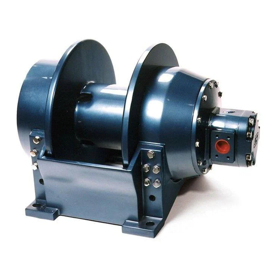
Page 4: General Description
DESCRIPTION OF THE MODEL H25 GENERAL DESCRIPTION: The PULLMASTER Model H25 is a planetary, hydraulic winch with reversing or lowering speed 4.67 times faster than forward or hoisting speed. The main components of this unit are: hydraulic gear motor multi-disc brake with static and dynamic function... -
Page 5: Hydraulic Motor
EXPLANATION OF MODEL CODING X - XX - XX - XX X - X XXXX BASIC UNIT SERIES H = Rapid reverse SIZE OF UNIT REDUCTION RATIO Only used for non standard reduction ratios TYPE OF BRAKE Automatic brake, clockwise drum rotation, internal circulation flow Automatic brake, external brake release, clockwise drum rotation, internal circulation flow Automatic brake, external brake release, counterclockwise drum... - Page 6 HYDRAULIC MOTORS FOR HIGH PRESSURE HYDRAULIC SYSTEMS: The operating pressure of the PULLMASTER Model H25 planetary winch is limited to 2500 psi (172 bar). For hydraulic systems operating with a higher range of hydraulic pressure, the winch can be supplied with a hydraulic piston motor, which will provide for the same basic performance in terms of line pull and line speed capacity.
-
Page 7: Specifications
SPECIFICATIONS Performance specifications are based on standard hydraulic motor, gear ratio and cable drum with 7/8 inch diameter wire rope. For other cable drums refer to APPENDIX A. For other reductions or motors, refer to supplement inside back cover. Performance specifications for winches supplied with optional motors are provided in attached supplement. -
Page 8: Performance Graphs
PERFORMANCE GRAPHS PG-H25-C LINE PULL VS. OIL PRESSURE NOTE: MAX. ALLOWABLE LINE PULL WHEN LOWERING: jjlkjalkf Bare drum 5,357 lb 23.8 kN Full drum 3,778 lb 16.8 kN LINE PULL - kN 2500 2000 1500 1000 5000 10000 15000 20000... - Page 9 CIRCULATION RETURN LINE SUPPLIED WITH EXTERNAL (MUST GO DIRECT TO RESERVOIR) BRAKE RELEASE OPTION CIRCULATION SUPPLY LINE M25: 5 (US) GPM [19 L/MIN] H25: 7 (US) GPM [26 L/MIN] (EXTERNAL CIRCULATION MODELS ONLY) CONTROL VALVE (MOTOR SPOOL) 4-WAY SPRING RETURN TO CENTER...
- Page 10 (see SPECIFICATIONS). Usually, a pressure HYDRAULIC FLUID: relief is part of the hydraulic control valve. Where this The hydraulic fluid selected for use with PULLMASTER is not the case, a separate pressure relief valve must planetary winches should be a high grade, petroleum be installed and set at the recommended maximum based fluid, with rust, oxidation and wear resistance.
-
Page 11: Installation Instructions
RESULT IN PROPERTY DAMAGE, SEVERE INJURY OR DEATH. The initial installation or mounting of a PULLMASTER planetary winch is critically important for proper operation and performance. If the winch is mounted to an uneven surface, the centre line of the unit can be distorted to a point where the winch will not operate in either direction. - Page 12 1492-1/2, prEN 1677-1/3 and other relevant product standards 1) The cable drum of the PULLMASTER planetary winch has two cable anchor slots, one for clockwise and one for counterclockwise hoisting. Standard rotation for hoisting is clockwise when looking at the hydraulic motor of the unit.
-
Page 13: Troubleshooting
TROUBLE SHOOTING GENERAL: In most cases, when the hydraulic winch does not perform satisfactorily, the cause of malfunction is found somewhere in the hydraulic circuit. Before the winch is removed from its mounting and disassembled, all of the hydraulic circuit components should be checked for proper function. IMPORTANT: The hydraulic oil volume relates to the line speed or rpm of the winch. - Page 14 Refer to the SERVICE INSTRUCTIONS if it becomes necessary to disassemble the Model H25 winch. PAGE 12 251 REV.970601...
- Page 15 For the majority of required service or repair work, disassembly is required only on the brake housing of the PULLMASTER Model H25 planetary winch. There are no special tools needed for the service or repair work and no adjustments or calibrations are necessary. Proceed with the disassembly as follows:...
- Page 16 800, and the port end cover, item 870, are standard parts of the hydraulic motor, having a 3 inch gear section. All of these parts can be ordered from PULLMASTER or Authorized Distributors/Dealers in Canada, the United States and in most overseas areas.
- Page 17 SERVICE INSTRUCTIONS CONTINUED should be intact and grooved. If any damage is detected, replace friction and divider plates as a set. 7) Remove brake spacer, item 712. 8) Remove the drain plug, item 121, from the end cover, item 120, and drain the lubricating oil from the final drive assembly and the cable drum interior.
- Page 18 SERVICE INSTRUCTIONS CONTINUED 2) Discard O-ring, item 123, and inspect planet hub stopper, item 126, and sungear stopper, item 122, for excessive wear. Replace planet hub stopper if less than .30 inch and sungear stopper if less than .21 inch thick.
- Page 19 SERVICE INSTRUCTIONS CONTINUED fasten internal gear onto connecting shaft using circlip, item 431. 7) Reassemble primary planet hub assembly. Use grease to temporarily hold 20 loose rollers, item 423, in the bore of the planet gear, item 420. Verify placement of sungear stopper, item 444. Position thrust washers, item 421, on either side of the planet gear and press planet pin, item 410, into the final planet hub, item 400.
- Page 20 SERVICE INSTRUCTIONS CONTINUED 9) Slide the hydraulic motor assembly on the splined end of the motor drive shaft, item 730, and line up the pressure transfer holes of the brake housing and the motor adaptor. Tighten 12 capscrews, item 821, and lockwashers, item 823, one turn at a time to evenly compress springs.
-
Page 21: Recommended Maintenance
5) Reassemble the winch as per instructions. 6) Follow INSTALLATION and OPERATING INSTRUCTIONS when returning winch to its mounting. When ordering parts for the PULLMASTER Model H25 planetary winch, always quote the complete model and serial number of the unit. - Page 22 PARTS REFERENCE - FINAL DRIVE DESCRIPTION ITEM NO. QTY. PART NO. 20399 FINAL HOUSING 25332 BALL BEARING # 6024 20460 BEARING RETAINER 25148 OIL SEAL 20400 END COVER 25237 PIPE PLUG 3/4 - 14 NPT 19036 SUNGEAR STOPPER 25340 O-RING -281 15" ID 1/8" CS 20416 RETAINING RING 20418...
- Page 23 FINAL DRIVE GROUP G1000-A Groups drawings may reference more parts than are actually present in a specific assembly. Parts that are referenced on the drawing but are not on the PARTS REFERENCE list should be ignored. 251 REV.950201 PAGE 21...
- Page 24 PARTS REFERENCE - BRAKE GROUP DESCRIPTION ITEM NO. QTY. PART NO. 20404 PLANET HUB 20417 RETAINING RING 20369 PLANET PIN 25004 CIRCLIP ROTOR CLIP C-87 25091 CIRCLIP ROTOR CLIP SH-87 20370 PLANET GEAR 25068 THRUST WASHER TORRINGTON # TRA 1423 25270 LOOSE ROLLER 5/32 X 1.25 TORRINGTON # E151 - Q 20411...
-
Page 25: Brake Group
BRAKE GROUP G1004-A Group drawings may reference more parts than are actually present in a specific assembly. Parts that are referenced on the drawing but are not on the PARTS REFERENCE list should be ignored. 251 REV.950201 PAGE 23... - Page 26 PARTS REFERENCE - MOTOR GROUP DESCRIPTION ITEM NO. QTY. PART NO. 25081 CAPSCREW - HEX HEAD 1/2 - 13 NC X 1.5 GRADE 5 25014 LOCKWASHER 1/2" 20415 MOTOR DRIVE SHAFT 25288 CIRCLIP ROTOR CLIP C-112 20401 MOTOR ADAPTOR 25127 O-RING -013 7/16"...
-
Page 27: Motor Group
MOTOR GROUP G1002-D Group drawings may reference more parts than are actually present in a specific assembly. Parts that are referenced on the drawing but are not on the PARTS REFERENCE list should be ignored. 251 REV.970601 PAGE 25... -
Page 28: Installation Dimensions
INSTALLATION DIMENSIONS I1001-1-D PAGE 26 251 REV.051117... -
Page 29: Hydraulic Motors
INSTALLATION DIMENSIONS I1001-2-A & I1001-3-A Dimensions in inches (Dimensions in millimeters) DRUM CODE 10.0 17.0 11.0 19.9 19.9 21.0 18.500 28.6 31.0 11.38 20.8 17.750 20.8 (254) (432) (279) (218) (505) (505) (533) (469.90) (726) (787) (289) (225) (527) (450.85) (527) 10.0 24.0... -
Page 30: Assembly Drawing
ASSEMBLY DRAWING G1000 & G1002 & G1004 PAGE 28 251 REV.980615... - Page 31 APPENDIX A LINE PULL HOISTING MAXIMUM LOWERING LINE SPEED AT MAXIMUM ALLOWABLE LINE SPEED LUBRICATING WIRE ROPE STORAGE CABLE DRUM SIZES PRESSURE AT MAXIMUM LINE PULL AT MAXIMUM VOLUME INCHES FEET DRUM VOLUME* - HOISTING* - LOWERING* VOLUME* REQUIRED CODE (MILLIMETERS) (METERS) POUNDS...
- Page 32 APPENDIX B ITEM 550 / 552 CABLE BEARING FINAL DRUM CODE BASE DRUM FLANGE SUNGEAR 20409 20395 20402 20671 20409 20396 20402 20444 20408 20393 20402 20443 20407 20391 20402 20403 20687 20688 21841 20690 - 10 20687 20935 20402 20937 - 14 20408...
-
Page 33: Part Numbers
APPENDIX C BRAKE CODE - 10 ITEM PART DESCRIPTION PART NUMBERS SHUTTLE 20849 20849 20849 20849 CIRCULATION 20456 20456 20456 20456 VALVE 1/4-18 NPT 25031 25031 25031 25031 PIPE PLUG 1/8-27 NPT 25040 25040 25040 25040 PIPE PLUG 1/8-27 NPT PIPE 25622 25622... -
Page 34: Bolt Torque Chart
BOLT TORQUE CHART BOLT DIAMETER TORQUE TORQUE Inches lb-ft 5/16 7/16 9/16 1085 1000 1356 1200 1627 1500 2034 NOTE: Unless otherwise specified, torque bolts per above chart. PAGE 32 251 REV.950201...
Need help?
Do you have a question about the H25 and is the answer not in the manual?
Questions and answers