Table of Contents
Advertisement
Advertisement
Table of Contents
Troubleshooting

Subscribe to Our Youtube Channel
Summary of Contents for Andrew ION-B Series
- Page 1 -B Series User Manual rel. 24-10...
- Page 3 © Copyright Andrew Wireless Systems Srl Andrew Wireless Systems Srl Via Pier De Crescenzi 40 48018 Faenza, Italy Tel: +39 0546 697111 Fax: +39 0546 682768 This publication is issued to provide outline information and is not aimed to be part of any offer and contract.
-
Page 4: Table Of Contents
Index Introducing ION-B Introducing ION-B The Features Brief Description of ION-B ION-B Features ION-B Typical Applications 2. Equipment Overview Equipment Overview Introduction 2.2. The ION-B Remote Unit and its relevant accessories 2.3. The ION-B Master Unit 2.4. ION-B additional options 2.5. -
Page 5: Quick Troubleshooting Procedure Dry-Contact Troubleshooting Fibre Optic Dl Troubleshooting
Quick troubleshooting procedure Dry-contact troubleshooting Fibre optic DL troubleshooting 3.4. Case R Remote Unit Dimensions and Weight RF ports: Optical ports: Visual alarms: External alarms Power supply: Warnings (to be read before Remote Units are installed) Dealing with optical output ports Choosing a proper installation site for the Remote Units Handling optical connections TFAx Case-R installation... - Page 6 -48 Vdc TPRN ports RS232 serial port RS485 port Sub-D 15 poles male connector Name Meaning TPRN alarms Warning (recommended for system designing and installing) Providing correct heat dissipation Minimizing equipment costs TPRN Installation TPRN Troubleshooting 4.2. Fast MiniRack, TPRF31 Major TPRN Features Dimensions and Weight On/Off Switch and Power Supply...
- Page 7 Warnings TLCN2 Installation 4.5. Four-way Splitter/Combiner,TLCN4 Description: RF Ports: TLCN4 Main Applications TLCN4 Insertion Loss Warnings TLCN4 Installation 4.6. RF Dual Band Coupler TLDN Description: RF Ports TLDN Main Applications TLDN Insertion Loss Warnings TLDN Installation 4.7. RF Tri Band Coupler TLTN Description: TLTN Models RF orts...
- Page 8 5. Confi guration Examples Confi guration Examples Introduction 5.2. Multi-operator applications 5.3. Multi-sector applications 5.4. Fast MiniRack applications Warning and Safety Requirements Warning and Safety Requirements Environmental Conditions Installation Site Features Safety and Precautions During Installation or Maintenance Power Supply Connection Safety and Precautions for Lasers Health and Safety Warnings RSS Canadian standards...
- Page 9 MN024-010...
-
Page 10: Introducing Ion-B
Introducing ION-B ION-B User Manual... -
Page 11: Introducing Ion-B
1. Introducing ION-B 1.1 The Features ION-B is an innovative platform designed in order to provide an effective and fl exible coverage to a large variety of indoor scenarios. Thanks to its high modularity, its low power consumption, and its full-transparency to protocols and modulation formats, ION-B is the perfect plug&play solution to distribute any wireless standard (including GSM, GPRS, EDGE, CDMA, W-CDMA, and WLAN IEEE 802.11b/g) to the in- building environments requiring reliable and interference-free communications, as well as high... -
Page 12: Ion-B Features
• a variable number of Remote Units (TFAx), whose function is feeding the antenna passive network; • a proper number of indoor antennas, suitable to provide radio coverage to the area. ION-B is fully compatible with any type of indoor antennas; •... -
Page 13: Ion-B Typical Applications
B equipment provides RF splitters/combiners, cross band couplers, attenuators, and duplexers for UL/DL paths, thus allowing maximum in design fl exibility; • high reliability: high MTBF (Mean Time Between Failure). 1.4 ION-B Typical Applications Due to its unique features, the ION-B is an ideal solution for radio coverage in a variety of situations: •... - Page 14 wideband interconnect link option, distances of 20km can be reached. Moreover, these environments require gradual investments, because initially operators tend to provide radio coverage only in the busiest areas, and then extend it in order to reach complete coverage later. The modularity of the ION-B helps operators to gradually expand the system.
- Page 15 MN024-010...
-
Page 16: Equipment Overview
2. Equipment Overview ION-B User Manual... -
Page 17: Equipment Overview
2. Equipment Overview 2.1 Introduction The basic components of an ION-B system (please refer to fi g. 2.1.) are the following: • a Master Unit, able to bring the mobile signals from the BTS to different Remote Units and vice-versa, thus remotising the distribution and collection of any mobile signals via fi beroptic cables;... - Page 18 The Remote Unit (TFAx) is a device which provides optical-to-electrical downlink conversion and electrical-o-optical uplink conversion, thus allowing a bidirectional transmission of signals between the Master Unit and the remote antennas. It is available in 3 different power confi gurations (Low/Medium/High), housed by 4 different architectures (Case B, Case R, Case R2 and Case F), so as to fulfi...
-
Page 19: The Ion-B Master Unit
2.3. The ION-B Master Unit The ION-B Master Unit is a widely-fl exible system. Its modular feature allows it to be developed both for simple installation-friendly, unobstrusive applications to complex installations, involving a virtually unlimited number of subracks, and distributed through several fl oors of a building or through a 20km distance. - Page 20 The variable RF attenuators (TBSI): they provide independent attenuations (adjustable from 0 to 30dB, with 1dB steps) on uplink and downlink RF paths, and allow the designer to optimize the signal level close to the BTSs. TBSI is an override attenuator, its dimensions are: Width = 7TE, Height = 4HE.
- Page 21 • To connect several BTSs to a master optical TRX. In downlink, the TLCN2 (or TLCN4) combines the RF signals coming from different BTSs into a common RF signal, entering the master optical TRX. In uplink, the TLCN2 (or TLCN4) splits the composite RF signal coming from a master optical TRX into 2 (or 4) RF signals entering different BTSs.
-
Page 22: Ion-B Additional Options
• A Remote Powering Unit (TRSN), providing -48Vdc power supplying through composite fi beroptic/copper cables Table 2.3 shows an overview of these ION-B accessories and of the corresponding Andrew bulletins you should refer to for further information. Fig. 2.12: TSUN supervision unit, available both as a plug-in card (a) and as a stand-alone module (b) ;... - Page 23 Although the following table tables show a brief overview of the main ION-B additional options, we strongly recommend you to contact your reference Andrew Salesperson or Product Line Manager in order to have For a full overview of the ION-B options,...
-
Page 24: Block Diagrams
2.5. Block Diagrams In order to better understand the functionalities of the different units and modules, some block diagrams of the ION-B system are presented here. The core of an ION-B system is the ION-B master unit, which generally develops through a passive section (providing Level adjustments, Signal splitting/combining, and Band coupling), followed by an Electrical/Optical conversion (allowing the signal to be distributed through fi... - Page 25 Although TPRF31 proves to be very fl exible, complex distribution systems usually can be better served by rack-based ION-B Master Units: such ION-B installations are based on one or more TPRN-subracks, thus exploiting the wide range of ION-B passive cards (TDPN, TMP, TBSI, TLCN2, TLCN4, TLTN, TLDN), in order to build the passive network which best matches the costumer’s needs.
- Page 26 Fig. 2.14: Block diagram of an ION-B confi guration supporting a triple-band system with DUPLEXED base stations. ION-B User Manual...
- Page 27 Fig. 2.15: Block diagram of an ION-B confi guration supporting a triple-band system with NOT DUPLEXED base stations. MN024-010...
- Page 28 ION-B User Manual...
-
Page 29: Tfax Remote Unit
3. TFAx Remote Unit MN024-010... -
Page 30: Introduction
3.1. Introduction The Main Tasks of the TFAx Unit: Downlink (DL): • Optical-to-RF conversion of the input optical signal • Automatic Gain Control (AGC) of each converted signal, in order to compensate optical losses; • RF amplifi cation: the converted RF signal is boosted in order to maintain a good signal-to- noise ratio •... -
Page 31: Different Types Of Remote Units
Sales representative or check it on the offi cial ION-B Brochure (see fi g. 3.1.2),. As in fi g. 3.1.2, the “TFAM 91/18/20” Remote Unit proves to be described in the Andrew bulletin PA-100508-EN. Look through the Remote Unit’s dedicated bulletin in order to get all of the technical specifi... - Page 32 TFAM Case A ION-B User Manual...
-
Page 33: Case R Remote Unit
3.3. Case A Remote Unit TFAM Case A Dimensions and Weight: Dimensions: 38 x 240 x 200 mm (1.5 x 9.4 x 7.9 inches) Weight : please refer to the Remote Unit dedicated bulletin in order to discover any updated data regarding the weight of the case A Remote Unit LED alerts Green =power ON;... -
Page 34: Visual Alarms
Visual Alarms: TFAM Two control LEDs are provided on the TFAx front side (Fig. 3.2.2). The green LED indicates the Case A power supply status, while the red LED indicates any major Remote Unit failures (please refer to Table 3.4). Led colour Meaning Low optical power at DL input... -
Page 35: Warnings (To Be Read Before Remote Units Are Installed)
TPSN external power supplies provide the Case A Remote Unit with +5Vdc power, by means of a 3-pole connector. TFAM Case A Warnings (to be read before Remote Units are installed) Dealing with optical output ports The TFAx Remote Unit contains semiconductor lasers. Invisible laser beams may be emitted from the optical output ports. -
Page 36: Tfax Case-R Installation
APC adapters open, as they attract dirt. Unused optical connectors must always be covered with their caps. TFAM • Do not touch the connector tip. Clean it with suitable material before inserting each Case A connector into its sleeve. If connector tips require cleaning, use only pure ethyl alcohol. TFAx Case A installation The Case B Remote Unit is able to be fi... - Page 37 created by any other piece. The Remote Unit and its external power supply should be mounted so as to avoid reciprocal heating. Side-by-side confi guration is suggested (Fig. TFAM 3.2.6 a,b) Case A • Remote Units are provided with cooling fi ns which allow the optimization of heat dissipation.
-
Page 38: Installation Of The Case A Remote Unit With The Tka04 Installation Kit
connect the external adapter to the -48 Vdc supply (Fig. 3.2.6 b). If the Remote Unit is 90/264 Vac-powered, fi x the 90/264 Vac plug (included) onto a power cord (not TFAM included), and use this cable to connect the external adapter to the mains (Fig. 3.2.6 a). Case A 10. - Page 39 Remote Unit and its power supply: • Under no circumstances should any piece of equipment be affected by the heat TFAM created by any other piece. The Remote Unit and its external power supply should be Case A mounted so as to avoid reciprocal heating. Side-by-side confi guration is suggested (Fig. 3.2.8 a,b) •...
- Page 40 TFAM Case A Figure 3.2.9 : Case A layout with waal anchor quotes ION-B User Manual...
- Page 41 TFAM Case A Figure 3.2.10: Layout of the 220Vac/+5Vdc power adapter, provided with Case A Remote Units. MN024-010...
- Page 42 TFAM Case A Figure 3.2.11: Layout of the TKA installation kit for TFAx Remote Unit, Case A. ION-B User Manual...
- Page 43 TFAM Case A Figure 3.2.12: Mounting the TFAx Case A Remote Unit with a TKA installation kit. Please not that the Figures do not show the mounting of the external power supply.adapter. MN024-010...
-
Page 44: Tfax Case R Troubleshooting
TFAx Case A Start-Up Before the TFAx Remote Unit is switched on, make sure that: • the modules hosted in the master unit have been connected to each other with RF jumpers, according to the system design • every TFLN master optical TRX has been connected to its Remote Units •... -
Page 45: Dimensions And Weight
3.4. Case B Remote Unit Dimensions and Weight: TFAM Case B Dimensions: 38 x 240 x 240 mm (1.5 x 9.4 x 9.4 inches) Weight : please refer to the Remote Unit dedicated bulletin in order to discover any updated data regarding the weight of the Case B Remote Unit LED alerts Green =power ON;... -
Page 46: Rf Ports
RF ports: • 2 RF antenna ports, transmitting/receiving signals to/from distributed antennas. RF antenna ports are duplexed N-female connectors. These RF ports can be connected to the antennas either directly (ie. through RF jumper cables) or through splitters, thus TFAM Case B allowing more antennas to be fed. -
Page 47: Power Supply
Power Supply Case B Case B, Power version Remote Units are provided with different types of TPSN external power supplies (Fig. 3.3.4 a,b), available either for universal mains (90 to 264) or for negative supply. (-72 to -36 Vdc). TFAM TPSN external power supplies for Case-B Remote Units provide the with +5Vdc power, by... -
Page 48: Warnings (To Be Read Before Remote Units Are Installed)
Warnings (to be read before Remote Units are installed) Dealing with optical output ports TFAM The TFAx Remote Unit contains semiconductor lasers. Invisible laser beams may be emitted Case B from the optical output ports. Do not look towards the optical ports while equipment is switched on. -
Page 49: Tfax Case-R2 Installation
• Do not touch the connector tip. Clean it with suitable material before inserting each connector into its sleeve. If connector tips require cleaning, use only pure ethyl alcohol. TFAM TFAx Case B installation Case B The Case B Remote Unit is able to be fi xed to walls, false ceilings or other fl at vertical surfaces, either directly or through a TKA04 installation kit (optional). - Page 50 • Remote Units are provided with cooling fi ns which allow the optimization of heat dissipation. In order for them to function properly, the mounting environment should allow for the necessary air changeover • It is strongly recommended not to mount the external power supply on a horizontal TFAM surface because this position does not allow heat dissipation.
-
Page 51: Installation Of The Case B Remote Unit With The Tka04 Installation Kit
Installation of the Case B Remote Unit WITH the TKA04 installation kit The TFAx Case B kit includes: 1. a Remote Unit TFAx 2. a 50 Ω load TFAM 3. a TPSN external power supply adapter (86 to 264 Vac or -72 to -36 Vdc, according to the Case B chosen model) 4. -
Page 52: Tfax Case R2 Start-Up
in a vertical position with the power socket downwards (see Fig. 3.3.8 a,b). Once you have chosen the position of the Remote Unit mounting case, please follow these instructions: TFAM Case B 1. Unscrew the 4 screws which lock the lower cover of the TKA04 wall bearing (see Fig. 3.3.12 a) 2. - Page 53 TFAM Case B Figure 3.3.9 : Case B layout with wall anchor quotes MN024-010...
- Page 54 TFAM Case B Figure 3.3.10: (a) Layout of the 220Vac/+5Vdc power adapter, provided with Case B Remote Units. (b) Layout of the 220Vac/+5Vdc power adapter, provided with Case B Remote Units. ION-B User Manual...
- Page 55 TFAM Case B Figure 3.3.11: Layout of the TKA installation kit, provided with Case B Remote Units. MN024-010...
- Page 56 TFAM Case B Figure 3.3.12: Mounting the TFAx Remote Unit with a TKA installation kit. Please not that the Figures do not show the mounting of the external power supply.adapter. ION-B User Manual...
-
Page 57: Tfax Case B Troubleshooting
Once the TFAx has been switched on, its behaviour can be summarized as per the following indicators: 1. When the Remote Unit is turned on, both the LEDs upon the warm side turn on for a TFAM couple of seconds Case B 2. - Page 58 ALARM CODE SUPERVISION RELÉ PRIORITY ALARM ACTION (TSUN ACTIVE LED PRIORITY LEVEL DESCRIPTION RECOMMENDED description) LEVEL (subrack) Antenna DC ALWAYS OK loop alarm TFAM The optical power received on the Check the DL fi bre Case B DL optical DL is too low and MAJOR and the TFLN laser MAJOR...
- Page 59 As shown in the previous table, the same red LED switches on to reveal any major failures. By following the next troubleshooting procedure, it will be possible to better understand what problem has occurred. TFAM Case B Note: Each Remote Unit is provided with an AGC system which kicks in after the optical-to-RF conversion.
- Page 60 Rearrange the optical path to avoid sharp bends. If necessary, Is any dry contact replace the optical cable start connected to some with a longer one external equipment? TFAM Case B Is the red LED upon the TFAx still ON?? Fix better the Are SC-APC SC-APC...
- Page 61 Rearrange the optical path to avoid sharp bends. If necessary, Is any dry contact replace the optical cable start connected to some with a longer one external equipment? TFAM Case B Is the red LED upon the TFAx still ON?? Fix better the Are SC-APC SC-APC...
-
Page 62: Quick Troubleshooting Procedure
As shown in the previous table, the same red LED switches on to reveal any major failures. By following the next troubleshooting procedure, it will be possible to better understand what problem occurred. TFAM Case B Quick troubleshooting procedure (The following procedure is summarized by the fl ow-chart in Fig. 3.3.14a) If the red LED is LIT, please follow these steps: 1. -
Page 63: Fibre Optic Dl Troubleshooting
Fibre optic DL troubleshooting (The following procedure is summarized by the fl ow-chart in Fig. 3.3.14c) 1. Check to see if there are any points in which fi bres are experiencing a short radius of curvature. In these cases, rearrange the optical path in order to avoid sharp bends (if TFAM necessary, replace the optical cable with a longer one). - Page 64 TFAM Case R ION-B User Manual...
-
Page 65: Dimensions And Weight
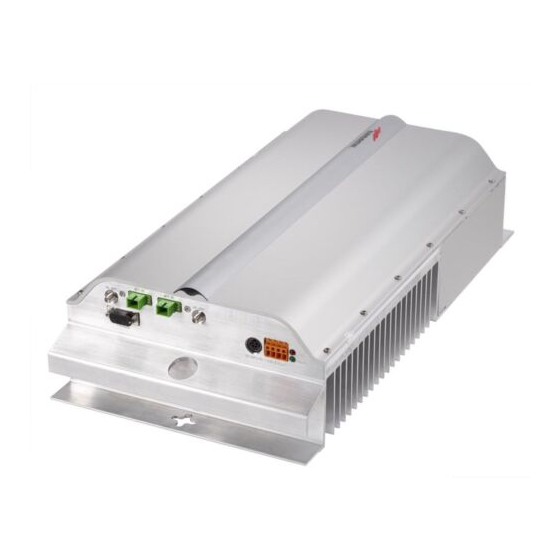
3.5. Case R Remote Unit Dimensions and Weight Dimensions: mm. 564 x 255 x 167 (inches 21.5 x 10 x 8.1) TFAM Weight: please refer to the Remote Unit dedicated bulletin in order to know the Case R updated data about the weight of your case-R Remote Unit. Figure 3.4.1: ION-B, Case-R Remote Unit: (a) Remote Unit view;... -
Page 66: Rf Ports
RF ports: • 1 RF antenna port, transmitting/receiving signals to/from distributed antennas. This RF antenna port is a duplexed N-female connectors. The port can be connected to the antenna either directly (ie. through RF jumper cables) or through splitters, thus allowing more antennas to be fed. -
Page 67: Power Supply
Power supply: Case-R Remote Unit is provided with a TPSN external power supply (Fig. 3.4.4 a,b), available either for universal mains (90 to 264) or for negative supply. (-72 to -36 Vdc). Before installing your Remote Unit, please check TFAM you have been provided with the proper external Case R power supply. -
Page 68: Tfax Case-F Installation
APC adapter open, as they attract dirt. Unused optical connectors must always be covered with their caps. • Do not touch the connector tip. Clean it with a proper tissue before inserting each connector into the sleeve. In case connector tips need to be cleaned, use pure ethyl alcohol. - Page 69 Figure 3.4.5: Mounting the Case-R Remote Unit, Steps (a) - (c). TFAM Case R MN024-010...
- Page 70 Figure 3.4.5: Mounting the Case-R Remote Unit, Steps (d) - (h). TFAM Case R ION-B User Manual...
- Page 71 Figure 3.4.5: Mounting the Case-R Remote Unit, Steps (i) - (l). TFAM Case R MN024-010...
-
Page 72: Tfax Case F Troubleshooting
the Remote Unit. The suggested installation position is side by side to the power supply or to the Remote Unit, using one of their M6 anchors already installed to support the splice box as well (please see Fig. 3.4.5g, 3.4.5h). NOTE: Take care not to bend the fi... - Page 73 3.6. Case-R2 Remote Unit Dimensions and Weight Dimensions: mm. 564 x 255 x 167 (inches 21.5 x 10 x 8.1) Weight: please refer to the Remote Unit dedicated bulletin in order to know the updated data about the weight of your case-F Remote Unit. TFAM Case R2 Figure 3.5.1: ION-B, Case-R2...
-
Page 74: Rf Ports
RF ports: • 1 RF antenna port, transmitting/receiving signals to/from distributed antennas. This RF antenna port is a duplexed N-female connectors. The port can be connected to the antenna either directly (ie. through RF jumper cables) or through splitters, thus allowing more antennas to be fed. -
Page 75: Power Supply
Power supply: Each case-R2 Remote Unit must be ordered with a proper TPSN external power supply (Fig. 3.5.4), available either for universal mains (90 to 264) or for negative supply. (-72 to -36 Vdc). Before installing your Remote Unit, please check you have been provided with the proper external power supply. - Page 76 APC adapter open, as they attract dirt. Unused optical connectors must always be covered with their caps. • Do not touch the connector tip. Clean it with a proper tissue before inserting each connector into the sleeve. In case connector tips need to be cleaned, use pure ethyl alcohol.
- Page 77 Figure 3.5.5: Mounting the Case-R2 Remote Unit, Steps (a) - (c). TFAM Case R2 MN024-010...
- Page 78 Figure 3.5.5: Mounting the Case-R2 Remote Unit, Steps (d) - (h). TFAM Case R2 ION-B User Manual...
- Page 79 Figure 3.5.5: Mounting the Case-R2 Remote Unit, Steps (i) - (l). TFAM Case R2 MN024-010...
- Page 80 to the Remote Unit, using one of their M6 anchors already installed to support the splice box as well (please see Fig. 3.5.5g). NOTE: Take care not to bend the fi bers too much. 5 - Now connect the RF cables, the optical connectors, and the power supply connector to the Remote Unit (Fig.
- Page 81 Note: if then discovery doesn’t start automatically, check through the LMT or the remote supervision whether it has been disabled (refer to LMT or remote Supervision System manuals for further information). ALARM CODE SUPERVISION RELÉ PRIORITY ALARM ACTION (TSUN ACTIVE LED PRIORITY LEVEL DESCRIPTION...
- Page 82 detection is directly carried out through LMT or Supervision System. ION-B modules are designed in order to exchange information each other: each RU constantly monitors the optical signal received from its TFLN unit, so as to control optical losses. Table 3.5.2 shows a brief description of the alarms related to a Cabinet R2 Remote Unit, with a reference to the corresponding alerted LEDs and to the actions to be carried out in the case of a fault.
- Page 83 Rearrange the optical path to avoid sharp bends. If necessary, Is any dry contact replace the optical cable start connected to some with a longer one external equipment? Is the red LED upon the TFAx still ON?? Fix better the Are SC-APC SC-APC connectors properly...
- Page 84 Rearrange the optical path to avoid sharp bends. If necessary, Is any dry contact replace the optical cable connected to some start with a longer one external equipment? Is the red LED upon the TFAx still ON?? Fix better the Are SC-APC TFAM SC-APC...
-
Page 85: Quick Troubleshooting Procedure
As shown in the previous table, the same red LED switches on to reveal any major failure. Following the troubleshooting procedure reported hereinafter it is possible to better understand what problem occurred. Quick troubleshooting procedure (The following procedure is summarized by the fl ow-chart in fi g. 3.5.7a) In case the red LED is ON, please follow these steps: 1. - Page 86 case, rearrange the optical path in order to avoid sharp bends (if necessary, replace the optical cable with a longer one). If TFLN red LED switches off, troubleshooting has been successfully carried out. Otherwise, follow next steps. 2. Check if SC-APC connectors are properly installed at both fi bre ends. In case they are not, fi...
- Page 87 3.7. Case F Remote Unit Dimensions and Weight Dimensions: mm. 564 x 255 x 167 (inches 21.5 x 10 x 8.1) Weight: please refer to the Remote Unit dedicated bulletin in order to know the updated data about the weight of your case-F Remote Unit. Figure 3.6.1: Case F Remote Unit (a) with connector panel (b) TFAM...
-
Page 88: Rf Ports
RF ports: • 1 RF antenna port, transmitting/receiving signals to/from distributed antennas. This RF antenna port is a duplexed N-female connectors. The port can be connected to the antenna either directly (ie. through RF jumper cables) or through splitters, thus allowing more antennas to be fed. - Page 89 85/264 Vac: Connector -36/-72 Vdc: Connector ground -48V Figure 3.6.3: Description of the 85/264 Vac inlet (a) and of the -36/-72 Vdc inlet (b) on a Case-F Remote Unit TFAM Case F Warnings (to be read before Remote Units are installed) Dealing with optical output ports The Case-F Remote Unit contains semiconductor lasers.
- Page 90 • Do not touch the connector tip. Clean it with a proper tissue before inserting each connector into the sleeve. In case connector tips need to be cleaned, use pure ethyl alcohol. TFAx Case-F installation Each case-F Remote Unit kit includes: •...
- Page 91 Figure 3.6.4: Mounting the Case-F Remote Unit Steps (a), (b) TFAM Case F MN024-010...
- Page 92 Figure 3.6.4: Mounting the Case-F Remote Unit Steps (c)-(d) TFAM Case F ION-B User Manual...
- Page 93 as soon as the local unit will be switched on (for further details about the start-up of the whole system, please refer to the section ”TFAx Case F start-up”). 5 - Close the unit, and fasten the 4 screws shown in fi g. 3.6.4c by using the torque key. TFAx Case F start-up Before the Case-F Remote Unit is switched on, make sure that: •...
- Page 94 Both LMT and Supervision System provide full information about the device causing the alarm. As a consequence, troubleshooting procedure can be very immediate when the failure detection is directly carried out through LMT or Supervision System. ION-B modules are designed in order to exchange information each other: each RU constantly monitors the optical signal received from its TFLN unit, so as to control optical losses.
-
Page 95: Quick Troubleshooting Procedure
levels. 0dBm The red LED switches on when the estimated optical losses are >4.5 dB, the AGC not being able to compensate these losses any more. Normal -3.5dBm Warning As shown in the previous table, the same red LED switches on to -4.5dBm reveal any major failure. - Page 96 Rearrange the optical path to avoid sharp bends. If necessary, Is any dry contact replace the optical cable start connected to some with a longer one external equipment? Is the red LED upon the TFAx still ON?? Fix better the Are SC-APC SC-APC connectors properly...
- Page 97 optical cable with a longer one). If TFLN red LED switches off, troubleshooting has been successfully carried out. Otherwise, follow next steps. 2. Check if SC-APC connectors are properly installed at both fi bre ends. In case they are not, fi x better SC-SPC connectors to adapters. If TFLN red LED switches off, troubleshooting has been successful.
- Page 98 ION-B User Manual...
-
Page 99: Rack-Based Master Unit
4. Rack-based Master Unit MN024-010... - Page 100 ION-B User Manual...
-
Page 101: Tprnx4 Subrack
4.1. TPRNx4 Subrack Major TPRN features The TPRNx4 is a 19”subrack where all the ION-B plug-in modules can be inserted. ION-B equipment provides a wide variety of these sub-rack models differentiated according to power supply. Each one is provided with: •... -
Page 102: 48Vdc Powered Sub-Rack (Tprn34)
Passive sub-rack (TPRN04) • TPRN04 is a passive sub-rack. It cannot supply power to any inserted module, and therefore is designed to host passive modules only. It can be useful in a multi-sub-rack system, in case the customer decides to put all the active modules in an active sub-rack, to be chosen among the following: 220 Vac powered sub-racks (TPRN14 / TPRN24) •... -
Page 103: Tprn Power Supply
TPRN power supply All the TPRN models refer to one of the following power supplies. Fuse Universal mains (85 to 264Vac, 50/60Hz). Figure 4.1.3: 85 to 264Vac inlet This connector is mounted on the TPRN back panel, both for the redundant version and the simple one. -
Page 104: Tprn Ports
converted to a +12Vdc voltage, feeding the active modules inserted into the TPRN. Figure 4.1.6: Rear view of the TPRN subrack with -48Vdc power supply Blue terminal: Blue terminal: -72 -36 Switch On/ Fuse TPRN ports The TPRN sub-rack is provided with a set of I/0 ports which allows the connection to any external device. -
Page 105: Rs485 Port
The connection baud rate can be set to 9600bps or 19200bps, by properly setting the dip-switch 5 standing on the interior TPRN backplane (fi g. 4.1.7). The baud rate setting through dip-switch 5 is shown in Table 4.1.1. Whichever baud rate you choose through dip-switch 5, remember that: •... -
Page 106: Pin
The TPRN sub-rack provides sub-D 15 poles male connector, shown in Fig. 4.1.5 As highlighted in Table 4.1.4, this connector provides: • 4 opto-isolated input ports which can be used to reveal any failure condition on external Address Address Dip-switch 1 Dip-switch 2 Dip-switch 3 Dip-switch 4... - Page 107 Supervision TSUN Alarm Alarm Active Action RELÉ Priority Codedescription) Description Recommended Priority Level Redundant supply active Backup power supply (only for redundant YELLOW MAJOR Return the unit MINOR activated power supply versions) There is a degradation Power Supply alarm on the power supply MAJOR Return the unit MAJOR...
-
Page 108: Tprn Alarms
TPRN alarms A full description of all TPRN alarms is provided by the Supervision System. Table 4.1.5 provides a brief description of the TPRN alarms, as they are reported by the LMT software. Warning (recommended for system designing and installing) Providing correct heat dissipation For correct use of the TPRN sub-rack, it is important to verify that: •... -
Page 109: Tprn Installation
TPRN Installation Figure 4.1.9: Some of the installation accessories provided with the Figure 4.1.10: The TPRN is provided TPRN subrack: (a) suitable power cord; (b) standard RJ-45 cable; with a screwing hole on each front (c) RS232 cable; (d) 1 Cd rom, including ION-B manuals TPRN corner, thus allowing proper fi... - Page 110 TPRN Start-up Before switching on the TPRN sub-rack, make sure that: • all necessary modules have been inserted • the modules have been connected to each other by RF jumpers, according to what has been planned during the system design •...
-
Page 111: Tprn Troubleshooting
TPRN Troubleshooting In case a TPRN sub-rack shows any problems, a more detailed status and alarm description is able to be provided through the remote supervision unit. A complete overview of TPRN alarms is provided in Table 4.1.5. A power supply degradation occurs in case the +12Vdc power falls below an in factory set threshold level. - Page 112 TPRF ION-B User Manual...
-
Page 113: Fast Minirack, Tprf31
4.2. Fast MiniRack, TPRF31 Major TPRN Features The TPRF31 is a low-cost mini rack which can host 2 ION-B single-slot cards, such as: 2 Master Optical Trx, thus being able to drive up to 8 ION-B Remote Units 1 Master Optical Trx (driving up to 4 ION-B Remote Units) and a proper ION-B card, working as a Point-of-Interface (POI) towards the BTS. -
Page 114: Dimensions And Weight
Dimensions and Weight Dimensions: 1 HE x 19”, maximum length 300 mm Weight: Please refer to bulletin PA-102187.1-EN Operating temperature: 0°C to 55°C On/Off Switch and Power Supply The TPRF31 fast MiniRack can be powered from -36 to -72 Vdc. A fuse is provided underneath the -48 Vdc connector, and must be replaced in case of failure (when it happens, the Supervision System will detect the failure). -
Page 115: Visual Alarms
the unused TPRF31 slots and of its TFLN ports. This operation should be perfomed during the initial system installation, after all of the TFLN units which are hosted by the TPRF31 MiniRack have stopped blinking (i.e., after they have fi nished the discovery phase: see the TFLN section of this User Manual for further clarifi... -
Page 116: Rs485 Port
Baud Rate [bps] Dip-switch 6 Dip-switch 7 9600 19200 Table 4.2.2 - Setting the RS232 baud- 57600 rate4 through dip-switches 6 and 7 115200 Figure 4.2.6 - Dip-switches on the TPRF31 backplane Whichever baud rate you choose through dip-switches 6 and 7, remember that: TPRF •... - Page 117 Address Address Dip-switch 1 Dip-switch 2 Dip-switch 3 Dip-switch 4 Dip-switch 5 (Dec) (Bin) 00001 00010 00011 00100 00101 00110 00111 01000 01001 01010 01011 01100 01101 01110 Reserved 01111 Reserved 10000 10001 10010 10011 10100 10101 TPRF 10110 10111 11000 11001 11010...
-
Page 118: Auxiliary Inputs
485 Bus Termination Load Dip-switch 8 Table 4.2.4 : Settiing the $85 Bus termination Not connected Load through Dip-Switch 8 Connected Power Supplying Ports The front side of the TPRF31 Fast MiniRack is provided with 4 power supplying ports, conveying the -48Vdc power supply to up to 4 ION-B Remote Units Please refer to Bulletin PA-101187-EN in order to check that the overall maximum power the TPRF31 provides to your Remote Units is below the overal maximum power supported by the... -
Page 119: External Alarms
Normally Closed (to CC) Normally Closed (to CC) Common Contact (CC) Alarm Outputs Inputs Figure 4.2.8: Auxiliary Inputs (b) and External Alarm Outputs (c) on the TPRF31 rear side (a). Description of the External Alarm Outputs (d). Alarm Outputs 1 and 2 (c) refers to Major and Minor alarms, respectively External Alarms The rear side of the TPRF31 Fast MiniRack is provided with two Alarm-output dry-contacts,... -
Page 120: Warning (Recommended When Designing Or Installing)
Warning (recommended when designing or installing) Providing correct heat dissipation For correct use of the TPRF31 sub-rack, it is important to verify if: • the TPRF31 has been mounted in a vertical position (please refer to the “TPRF31 Installation” section), the power supplying ports (located on the TPRF31, front side, Figure 4.2.7) have been turned upwards •... - Page 121 TPRF Figure 4.2.10: Turning the brackets of the TPRF31 Fast MiniRack, starting from the factory confi guration (a). Once the brackets have been turned and properly fi xed, the TPRF31 Fast MiniRack is ready for wall-mounting (d). Figure 4.2.11: Turning the brackets of the TPRF31 Fast MiniRack, starting from the factory confi...
-
Page 122: Mounting The Tprf31 On A Wall
Mounting the TPRF31 on a rack Firstly, insert the sub-rack into the cabinet, and apply 4 screws (not provided) in order to fi x it (Fig. 4.2.11). To correctly install the TPRN, the distance between the front door of the rack and the front side of the TPRF31 should be at least 15cm, otherwise optical cables and any eventual RF cables might be damaged when the cabinet door is closed. - Page 123 TPRF Figure 4.2.13: Mechanical Layout for wall-mounting the TPRF31 Fast MiniRack MN024-010...
-
Page 124: Tprf31 Troubleshooting
Once the TPRF31 sub-rack has been switched on, the system behaviour can be summarized by the following steps: • About 10sec after the TPRF31 sub-rack has been switched on, any TFLN modules housed in the TPRN itself begins a “discovery” phase in order to identify and collect status of the connected TFAx Remote Units. - Page 125 In case a TPRF31 sub-rack shows any problems, more detailed status and alarm descriptions are able to be provided through the remote supervision unit. A complete overview of the TPRF31 alarms is reported in the previous Table 4.2.14. Please note that: •...
- Page 126 TFLN ION-B User Manual...
-
Page 127: Master Optical Trx, Tfln
4.3. Master Optical TRX, TFLN Main tasks carried out by the TFLN module RF UL Auxiliary RF UL Port Main Port Downlink (DL): Status and Alarm LEDs ÿ RF-to-optical conversion of the input RF DL RF signal Main Port RF DL Auxiliary ÿ... -
Page 128: Tfln Visual Alarms
Label LED colour Signifi cance Green Power supply status OK General TFLN failure, it might be:- TFLN laser failure - UL or DL amplifi er failure - TFLN short circuit Low UL optical power received from Remote Unit 1 (fault in optical link 1 or Remote Unit 1 failure) Fig 4.3.2:... -
Page 129: Handling Optical Connections
Handling optical connections WRONG CORRECT • When inserting an optical connector, take care to handle it in order not to damage the optical fi bre. Optical fi bres have to be single- mode (SM) 9.5/125µm. • Typically, ION-B equipment is provided with SC-APC optical connectors. -
Page 130: Tfln Positioning
TFLN Positioning • In case no ventilation system has been installed, don’t insert more than 8 TFLN modules into the sub- rack. • In case more than 8 TFLN modules have to be housed in a TPRN sub- rack, it’s advisable to install the TPRN sub-rack inside a rack with forced Fig 4.3.6: ventilation. -
Page 131: Tfln Start-Up
Label LED colour Status Green (power supply is on) (no major failure affects TFLN operations) (no major failure affects corresponding Remote Unit or UL connection) (no major failure affects corresponding Remote Unit or UL connection) (no major failure affects corresponding Remote Unit or UL connection) (no major failure affects corresponding Remote Unit or UL connection) Table 4.3.2: LED alerts on the TFLN front panel TFLN Start-Up... - Page 132 Alarm Code Supervision Relé Active Action (TSUN Alarm description Priority Priority Recommended description) Level Level The optical power Check the UL1 received on the RX1 optical fi bre and the UL1 is too low and RED (LED1) CRITICAL MAJOR power fail Remote Unit laser can’t no more be status...
-
Page 133: Removing A Tfln Module
“discovery” phase to identify all connected Remote Units. This operation serves to collect all necessary information to be provided to the Supervision System. During the discovery phase, the TFLN general alarm (LED ) blinks while the other LEDs “ “ go on showing their previously detected status’. -
Page 134: Quick Troubleshooting Procedure
The previous table reports a brief description of the TFLN alarms, 0dBm together with a reference to the corresponding alerted LEDs. Normal -3dBm As the table shows, LEDs on the TFLN front panel signal all high Warning priority alarms while minor alarms, which detect critical situations -4dBm which should be checked and tested in order to avoid future Alarm... - Page 135 Is any red LED start ON upon the TFLN ?? Replace the Which red LED faulty TFLN. is ON ?? 1, 2, 3 or 4 Clean the corresponding SC-APC optical adapter and connector. Is the red LED upon the TFLN still ON?? TFLN Go to the...
- Page 136 Rearrange the optical path to avoid Is there any small sharp bends. If necessary, replace start radius of curvature the optical cable with a longer one of the fibre?? Is the red LED upon the remote unit still ON?? Are SC-APC Fix better the SC-APC connectors properly connectors.
-
Page 137: 4.4. Two-Way Splitter/Combiner, Tlcn2
4.4. Two-way Splitter/Combiner, TLCN2 Description: The TLCN2, a bidirectional 2-way splitter/combiner, provides two identical combining sections for UL and DL which can be used in the following ways: ÿ to combine 2 RF signals into a common RF output ÿ to split an RF input into 2 RF output signals It is a passive wideband module. -
Page 138: Tlcn2 Insertion Loss
More TLCN2 modules can be used in cascade connections. TLCN2 Insertion Loss The TLCN2 insertion loss varies slightly depending on the frequency bands, as shown in table 4.7. When designing the system, remember to take into account the insertion loss of the TLCN2, if 700-1400MHz 1400-2200MHz 2200-2500MHz... -
Page 139: Four-Way Splitter/Combiner,Tlcn4
4.5. Four-way Splitter/Combiner,TLCN4 Description: The TLCN4, bidirectional 4-way splitter/combiner, provides two identical combining sections for the UL and DL which can be used to: ÿ combine 4 RF signals into a common RF output ÿ split an RF input into 4 RF output signals It is a passive wideband module. -
Page 140: Tlcn4 Insertion Loss
More TLCN4 modules can be used in cascade connections. TLCN4 Insertion Loss The TLCN4 insertion losses vary slightly depending on the frequency bands, as shown in table 4.8. 700-1400MHz 1400-2200MHz 2200-2500MHz TLCN4 insertion loss 7.4 ± 0.4dB 8.0 ± 0.5dB 8.4 ±... -
Page 141: Rf Dual Band Coupler Tldn
4.6. RF Dual Band Coupler TLDN Description: The TLDN is a passive RF dual band coupler designed to distribute signals within the master unit when coming from different bands. Main operations carried out are: RF UL Common ÿ in downlink, it combines a low band RF Port signal (800MHz to 1000MHz) and a high band RF signal (1700MHz to 2200MHz) -
Page 142: Tldn Insertion Loss
(carrying different services) into an output signal entering the TFLN master optical ÿ TLDN fi lters the UL input coming from a TFLN master optical TRX into 2 UL outputs entering 2 different donor sources (carrying different services) TLDN Insertion Loss TLDN insertion loss = 1.0 ±... -
Page 143: Rf Tri Band Coupler Tltn
4.7. RF Tri Band Coupler TLTN Description: The TLTN is a passive RF tri band coupler designed to combine/split signals coming from different bands. RF UL Common Its main operations carried out are: Port ÿ in downlink, it combines a Low-band signal, RF DL a Middle-band signal and a High-band Common Port... -
Page 144: Tltn Main Applications
TLTN Ports Low-band Medium-band High-band TLTN Models: DL: 851-869 MHz DL: 935-941 MHz DL: 1710-2170 MHz UL: 806-824 MHz UL: 896-902 MHz UL: 1710-2170 MHz TLTN 36 (US LMR800 band) (US LMR800 band) (Generic high band) DL: 800-1000 MHz DL: 2110-2155 MHz DL: 1930-1995 MHz UL: 800-1000 MHz UL: 1710-1755 MHz... -
Page 145: 4.8. Rf Duplexer, Tdpn
4.8. RF Duplexer, TDPN Description: The TDPN is a frequency-dependent duplexer which combines downlink and uplink signals while maintaining isolation and stability. RF port for combined UL and DL signals This board has been designed to support duplexed Base Stations. RF Ports DL RF port •... -
Page 146: Tdpn Installation
As the module is band-dependent, be sure to order the proper single-band version(s). TDPN Installation Since the TDPN module doesn’t require any power supply it can be housed either in an active or a passive TPRN sub-rack. 1. Unpack the kit which includes ÿ... -
Page 147: Base Station Interface Tbsi
4.9. Base Station Interface TBSI DL RF input port Description (from donor source) The TBSI module adjusts the signal level between the donor source DL attenuation knob and the ION-B system. It has 2 independent variable attenuators to adjust both the uplink and downlink separately (please refer to the BriteTool manual to DL RF input port... -
Page 148: Tbsi Insertion Loss
TBSI Insertion Loss The TBSI insertion losses are described in table 4.9.1: When designing the system, remember to take into account the insertion loss of the TBSI. 800 MHz to 2000 MHz 2000 MHz to 2200 MHz TBSI insertion loss <... -
Page 149: Power Limiter Tmpx-10
4.10. Power Limiter TMPx-10 Description DL RF input port (from donor source) The TMPx-10 Power Limiter monitors the downlink input power and attenuates it by 10dB above a predetermined set point. The threshold is programmable through the Supervision System. The TMPx-10 power limiter is available in two versions, one for GSM 900 MHz / DCS 1800 MHz applications, and the other for UMTS 2100MHz. -
Page 150: Tmp Power Supply
TMP Power Supply Each TMPx-10 power limiter is supplied by the sub-rack back-plane (+12V). The power consumption of each TMPx-10 is 2W max. TMP Insertion Loss TMP insertion loss < 1.7dB. When designing the system, remember to take into account the insertion loss of the TMP. Warnings The overall input power must not exceed +35dBm. -
Page 151: Tmp Installation
GSM 900 MHz DCS 1800 MHz Fig. 4.10.2: Proper setting of the 2-pin jumper in the TMP2-10 Power Limiter: (a) GSM 900 MHz band ; (b) DCS 1800 MHz band. TMP Installation The TMP power limiter can be accomodated in any of the 12 slots of a TPRN active sub-rack. Note: In case a new TMP module has to be installed in a still working Master Unit, switch off the sub-rack before inserting the plug-in TMP module 1. -
Page 152: Removing A Tmp Module
Removing a TMP Module Switch off the Master Unit power supply and remove RF jumpers. Then: • unscrew the 4 screws and slowly remove the card. • put the removed TMP card in its safety box. • switch on the Master Unit power supply again and refer to TFLN Start-up section. TMP Troubleshooting In case a TMP power limiter has any problems, this will be easily revealed through LEDs on its front panel. - Page 153 TPRN backplane and you need to return the sub-rack. c. Otherwise the TMP power supply section is faulty. Return the unit. 2. In case the TPM red and green leds are lit, the RF level at the input port has exceeded the specifi...
- Page 154 ION-B User Manual...
- Page 155 5. Confi guration Examples MN024-010...
- Page 156 5. Confi guration Examples 5.1 Introduction Examples of ION-B confi gurations are demonstrated in the following pages, showing how the equipment is able to meet the demands of a variety of different applications, from the easiest to the most complex. Some Multi-operator and Multi-sector applications hosted by various ION-B subracks are explored here, as well as a s simple confi...
- Page 157 REMOTE UNITS Operator 1: Band Band 3 Operator 2: Band 1 Band 2 Band 3 Figure 5.1: Example of ION-B confi gurations for a Multi-operator application. MN024-010...
- Page 158 Operator 1, Operator 2, Operator 2, Operator 1 Band 1 + Operator 2 Band 1 Band 2 (e.g. 800-1000 MHz) Band 1 (e.g. 800-1000 MHz) (e.g. 1800-2000 MHz) TMP2-10 TBSI TDPN91 TLCN2 TDPN91 TBSI TMP2-10 TDPN18 TBSI at least 1HE Operator 1 : Band 1 + Band 3 Operator 2 : Band 1 + Band 2 + Band 3 TFLN...
- Page 159 5.3. Multi-Sector Applications For this example, a single operator is present, and 2-sector coverage is required. This confi guration refl ects a North American scenario, where the coverage needs involve the LMR 800 MHz, LMR 900 MHz, and the PCS 1900 MHz band. In this case, the entire area must be covered by: •...
- Page 160 REMOTE UNITS, PCS 1900 MHz sector REMOTE UNITS, REMOTE UNITS, LMR 800 MHz + LMR 900 MHz LMR 800 MHz + LMR 900 MHz 1st sector 2nd sector Figure 5.3: Example of ION-B confi guration for a Multi-sector application. ION-B User Manual...
- Page 161 LMR 800 MHz, LMR 900 MHz, PCS 1900 MHz LMR 900 MHz, LMR 800 MHz, Sector 1 Sector 1 (unsectorized) Sector 2 Sector 2 TDPN80 TBSI TDPN92 TBSI TDPN19 TBSI TLCN2 TDPN92 TBSI TDPN80 TBSI at least 1HE Sector 1 : LMR 800 MHz + LMR 900 MHz Sector 2 : LMR 800 MHz + LMR 900 MHz + + PCS 1900 MHz (unsectorized) + PCS 1900 MHz (unsectorized)
- Page 162 5.4. Fast MiniRack applications This last example demonstrates how the ION-B equipment is able to provide a simple solution to a situation where the same operator needs to provide coverage to 1 or 2 frequency bands. Such a situation can easily be solved by a Fast MiniRack application, housing a Master Optical Transceiver (TFLN) card and the appropriate Point-of-Interface (POI) card, to be chosen among the ION-B 1-slot cards.
- Page 163 Warning and Safety Requirements MN024-010...
- Page 164 6. Warning and Safety Requirements Environmental Conditions This equipment is designed to be installed in indoor environments. Operating temperature: +5 to +40°C Do not install in corrosive atmosphere or in critical environmental conditions such as hazardous classifi ed areas Installation Site Features A trained technician should carry out the installation of the master unit.
- Page 165 • take into consideration that each remote unit transmits an RF signal and the safety volume must be respected (refer to country regulations for safety volume magnitude); • remote units must be mounted according to installation instructions; • Weight and dimensions of case-F remote units should be carefully considered when choosing the installation site and positioning.
- Page 166 when working while the panel is open. When closing the panels, take care not to leave any tools inside the equipment, not to hurt your fi ngers, and not to trap clothes, bracelets, chains, or long hair. Never remove the cover from a TFAx remote unit or from a TPRN subrack when the power supply is ON.
- Page 167 Health and Safety Warnings Please be aware that each country or governmental body has established its own specifi c limits for RF exposure, to which the installation of any radiating antenna must conform. When installing your ION-B system, take care to comply to your local regulations and guidelines about RF exposure limits.
- Page 168 This equation includes the following factors: • G is the antenna gain (in dB) compared to isotropic radiating antennas; • P is the RF power that is present at the antenna connector (in W); • L is the total loss (in dB) between the TFAx remote unit output port and the antenna input port;...
- Page 169 The maximum allowed power density we have to comply with is: S = 50 W·m (typical ICNIRP reference level for occupational exposure to time-varied electric and magnetic fi elds) By reading the ION-B notes, we know that the output power per carrier at the TFAM antenna port is •...
- Page 170 • 26 dBm ± 1 ( +27 dBm maximum, equivalent to 0.501 W) in the UMTS band • The total output power at the antenna port is therefore: P = 0.158W x 2 + 0.200W + 0.501W = 1.345 W, By reading the cable specs, we get that RG223 cable losses can be estimated at 0.55 dB/m.
- Page 171 Warning Labels CLASS 1 laser product GROUND - Use this terminal for a safety ground connection for the equipment. When this equipment is no longer used, please do not throw it into a trash container as unsorted municipal waste. Waste electrical electronic equipment (WEEE) must be collected apart and disposed of according to the European Directives 2002/96/ EC and 2003/108/EC.
- Page 172 7. TECHNICAL SUPPORT ION-B User Manual...
- Page 173 48018 Faenza, Italy Tel: +39.0546.697111 Fax: +39.0546.682768 Useful information about the product is available on Andrew’s website: http://www.andrew.com/products/inbuilding/das/ion_b-series.aspx For further information about the product, please write to: Britecell@andrew.com For questions, comments or suggestions, go to following page on Andrew’s website: http://www.andrew.com/contactus/contact.aspx?ct=11 MN024-010...
- Page 174 ‘Return Material Authorisation’ (RMA request). Before sending any piece of equipment to the manufacturer, the following RMA request form is required to be sent via fax (+39 0546 682768) or via e-mail (Britecell@andrew.com). RMA REQUEST FORM Company name...
- Page 175 Appendixes MN024-010...
- Page 176 Appendix A: System Commissioning ® The following fl ow charts are a quick reference for the ION-B system installation and commissioning. The fi rst fl ow chart (see Fig. A.1) highlights the main steps for system installation and commissioning starting from the equipment unpacking up to the check of the coverage and call quality.
- Page 177 The previous fl ow chart contains the following cross references: • the master unit installation and cabling is described in more detail in the fl ow chart (Fig. A.3). It follows the fl ow of actions from the sub-rack mounting on the cabinet up to the settings and connections needed in case remote supervision has to be considered.
- Page 178 confi guration through LMT Software and/or remote supervision system. For more details on how to use the LMT and about TSUNx confi guration and start-up refer to their relevant manuals. • in case the system is not working properly, refer to the troubleshooting procedures reported in their relevant sections.
- Page 179 Switch them Are all the remote start units switched ON? Picture A.4: Flow-chart describing the system start-up steps Are all the Switch them subracks switched ON? Launch the discovery the LMT or remote Did the system supervision system discovery start? (please see the relevant manuals) Wait until the discovery...
- Page 180 The information reported hereinafter (table B.1) is aimed at allowing the costumer to recycle and dispose of the WEEE equipment according to environmental-friendly practices. These guidelines fall within Andrew’s efforts to increase re-use, recycling and other forms of recovery, leading to a reduction in the amount of waste going to landfi ll or incineration Fig.
- Page 181 Waste to be disposed of by approved companies (i.e., Hazardous Products Recyclable materials licensees for European Waste No. materials 160216) • Plastic (external case; inlet and • cables, fi beroptic cables, internal • Electrolytic TPSN Power Supply plug in the 220 Vac version) circuit boards, psu, inlet capacitors •...
Need help?
Do you have a question about the ION-B Series and is the answer not in the manual?
Questions and answers