
Subscribe to Our Youtube Channel
Summary of Contents for Sub-Zero Wolf ICBDF364G
- Page 1 subzero.com 800.222.7820 ICB Dual Fuel Service Manual General Information Installation Information Component Access & Removal Controls & Operation Technical Data Wiring Diagrams...
-
Page 2: Warranty Information
General Information International Dual Fuel (ICBDF) Series International Dual Fuel (ICBDF) Series WARRANTY INFORMATION This page contains a summary of the 2 & 5 Year Warranty that is supplied with every Wolf product, followed by details and notes about the warranties. TWO &... - Page 3 General Information International Dual Fuel (ICBDF) Series International Dual Fuel (ICBDF) Series INTRODUCTION This Technical Service Manual has been compiled to provide the most recent technical service information about this series. This information will enable the service technician to troubleshoot and diagnose malfunctions, perform nec- essary repairs, and return the appliance to proper operational condition.
- Page 4 General Information International Dual Fuel (ICBDF) Series International Dual Fuel (ICBDF) Series FEATURES, MODES AND SPECIAL COMPONENTS • Natural or LP gas rangetop with electric convection oven(s) • Blue porcelain oven interior • Stainless steel exterior finish • Platinum bezel surrounds all control knobs •...
-
Page 5: General Information
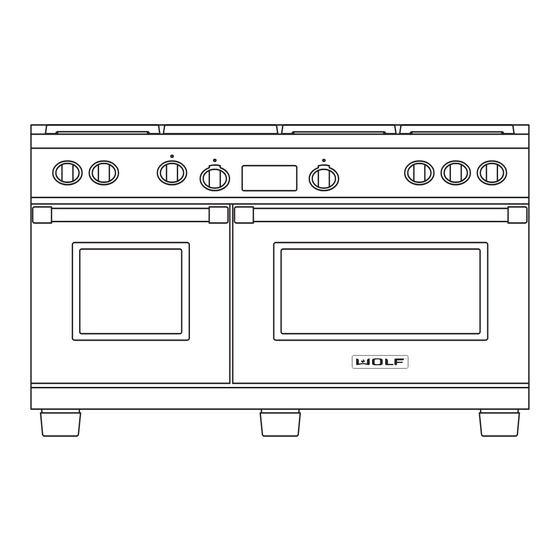
General Information International Dual Fuel (ICBDF) Series International Dual Fuel (ICBDF) Series MODEL NUMBER KEY Refer to this key for an example of the model numbers. Model: ICBDF C - LP Product Type ICBDF = International Dual Fuel Size 36 = 36 inch wide unit 48 = 48 inch wide unit 60 = 60 inch wide unit Surface Burners... - Page 6 General Information International Dual Fuel (ICBDF) Series International Dual Fuel (ICBDF) Series TOP CONFIGURATIONS OF ICB DUAL FUEL RANGES ICBDF366 36” Dual Fuel Range with Six Burners ICBDF364C 36” Dual Fuel Range with Four Burners and 11” Charbroiler ICBDF364G 36” Dual Fuel Range with Four Burners and 11” Griddle ICBDF486C 48”...
- Page 7 International Dual Fuel (ICBDF) Series Installation Information International Dual Fuel (ICBDF) Series INSTALLATION INFORMATION This section of the manual covers some of the installation issues that a service technician may need to know when servicing a Wolf ICB Dual Fuel Range. If additional installation information is needed after reviewing this section of the manual, please refer to the Installation Guide or contact the Wolf Appliance Customer Service Department.
- Page 8 International Dual Fuel (ICBDF) Series Installation Information International Dual Fuel (ICBDF) Series Gas Requirements Wolf ICB Dual Fuel Ranges are manufactured to work with natural gas or LP gas (Liquid Propane gas). The model / serial rating plate, located on the bottom of the control panel assembly just above the oven door on the far right, has information on the type of gas that should be used.
-
Page 9: Installation Information
International Dual Fuel (ICBDF) Series Installation Information International Dual Fuel (ICBDF) Series Gas Shut-off Valve The supply line must be equipped with an approved shut-off valve. This valve should be located in accordance to all national, local codes and ordinances (See Figure 3-1). -
Page 10: Installation Dimensions
International Dual Fuel (ICBDF) Series Installation Information International Dual Fuel (ICBDF) Series INSTALLATION DIMENSIONS 29 1 /2" (74.9) OVERALL DEPTH 27 1 /2" (69.9) 24 1 /4" (61.6) 35 7 /8" 36 7 /8" (91.1) (93.7) OVERALL 36 7 /8" (93.7) HEIGHT TO COOKING SURFACE... - Page 11 International Dual Fuel (ICBDF) Series Installation Information International Dual Fuel (ICBDF) Series Anti-Tip Bracket Installation Raise the unit to desired height using the rear leveling casters and adjusting the front adjustable legs. WALL SIDE PANEL Try fitting the unit in place to verify the correct height. Measure from the floor to the top of the range base flange on the back of the unit.
- Page 12 International Dual Fuel (ICBDF) Series Operation & Electronic Control International Dual Fuel (ICBDF) Series THEORY OF OPERATION A service technician should understand how a gas appliance operates before attempting to service the appliance. This section provides descriptions of the different types of fuel gases and explains gas heating values. A definition of specific gravity of gas is given along with its characteristics and effects.
- Page 13 International Dual Fuel (ICBDF) Series Operation & Electronic Control International Dual Fuel (ICBDF) Series Principals of Gas Combustion: Combustion When oxygen acts with a substance to produce large amounts of heat rapidly. Requirements for Combustion There are three required elements for combustion to occur; Fuel (Gas), Oxygen (Air) and Heat (Ignition Temperature, which for gas is between 1100°F/593°C and 1200°F/649°C).
- Page 14 International Dual Fuel (ICBDF) Series Operation & Electronic Control International Dual Fuel (ICBDF) Series Burner Components (Refer to Figure 3-1): Burner Cap - Provides the upper portion of the ports required to create a combustible mix and proper flame quality of the burner and the decorative top for the burner with a black porcelain coating.
- Page 15 International Dual Fuel (ICBDF) Series Operation & Electronic Control International Dual Fuel (ICBDF) Series Types of Burners: Blue Flame Burners All Wolf open surface burners, including the French Top burners are blue flame burners. With this type of burner, primary air is mixed with the fuel gas before the gas reaches the burner ports. An orifice is used to regulate gas flow to the burner and is sized to draw exact amount of air into the burner body.
- Page 16 International Dual Fuel (ICBDF) Series Operation & Electronic Control International Dual Fuel (ICBDF) Series OPERATION OF THE ICB DUAL FUEL RANGE Surface Burners A spark electrode ignites each surface burner. This control eliminates the need for continuous open flame pilots. For added safety and convenience, each burner is designed with an electronic re-ignition system.
- Page 17 International Dual Fuel (ICBDF) Series Operation & Electronic Control International Dual Fuel (ICBDF) Series Burner Lighting To light a burner push in and turn the corresponding control knob counter clockwise to the HIGH setting. You will hear “clicking” and see the burner ignite. Once the burner is lit, continue turning the knob counter clockwise to any one of the settings, HIGH through LOW.
- Page 18 International Dual Fuel (ICBDF) Series Operation & Electronic Control International Dual Fuel (ICBDF) Series CLEANING AND MAINTENANCE Part Identification Material Care Recommendation Burner Pan Exterior Finish General care: Use a clean cloth or sponge, wipe Porcelain Steel with warm water and mild detergent. Rinse and Although resistant to most dry immediately.
- Page 19 International Dual Fuel (ICBDF) Series Operation & Electronic Control International Dual Fuel (ICBDF) Series CLEANING AND MAINTENANCE Part Identification Material Care Recommendation Blank-Off Plate Stainless Steel Wash with hot water and detergent. Use a soap- (If Applicable) filled scouring pad to remove as much cooked-on soil as possible.
- Page 20 International Dual Fuel (ICBDF) Series Operation & Electronic Control International Dual Fuel (ICBDF) Series Time of Day Clock The clock can be visible on the display during all modes. To set clock, press CLOCK key on display panel, “CLOCK” will flash on and off. Next, press up or down arrow key to increase or decrease time.
- Page 21 International Dual Fuel (ICBDF) Series Operation & Electronic Control International Dual Fuel (ICBDF) Series COOKING MODES There are multiple cooking modes, each dedicated to give the best results for a specific kind of cooking. Most modes use temperature settings of 75°C (170°F) to 290°C (550°F). With exception of Broil, Convection Broil and Proof mode.
- Page 22 International Dual Fuel (ICBDF) Series Operation & Electronic Control International Dual Fuel (ICBDF) Series Broil Mode The top element is used to conduct an intense, radiant heat which browns one side of the food at a time. This mode is best for meats, fish and poultry pieces up to 1-inch thick.
- Page 23 International Dual Fuel (ICBDF) Series Operation & Electronic Control International Dual Fuel (ICBDF) Series Convection Bake Mode This mode combines heat from two convection elements with some heat from the hidden bake element. Two convec- tion fans circulate this heat within the oven cavity. The added heat from the hidden bake element make this mode ideal for pie baking.
- Page 24 International Dual Fuel (ICBDF) Series Operation & Electronic Control International Dual Fuel (ICBDF) Series Convection Roast Mode Heat from both convection fans, plus some heat from the broil element, intensifies the convective and radiant heating in this mode. This combination gently browns the exterior and seals in juices making it perfect for roasting tender cuts of beef, lamb, pork, and poultry.
- Page 25 International Dual Fuel (ICBDF) Series Operation & Electronic Control International Dual Fuel (ICBDF) Series OVEN FEATURES Dehydration Feature This feature allows for slowly drying out food for preserva- tion and other cooking uses. This requires an optional accessory package. To initiate Dehydration Feature, turn oven control knob bezel clockwise to CONV symbol (See Figure 3-40).
- Page 26 International Dual Fuel (ICBDF) Series Operation & Electronic Control International Dual Fuel (ICBDF) Series Delayed Start Feature This feature controls the automatic timing of the oven’s On and Off function. Set a cooking mode to start later in the day and turn off when the cooking is complete or set it to just to turn off at a preset time.
- Page 27 International Dual Fuel (ICBDF) Series Operation & Electronic Control International Dual Fuel (ICBDF) Series Sabbath Feature This feature allows for baking or keeping food warm while still adhering to the "no work" requirements on reli- gious Sabbath days. To initiate Sabbath Feature, first add food to the oven. Now, turn oven control knob bezel to either BAKE or ROAST mode (See Figure...
- Page 28 International Dual Fuel (ICBDF) Series Operation & Electronic Control International Dual Fuel (ICBDF) Series DIAGNOSTIC MODE Diagnostic Mode allows the Service Technician to inspect the functionality of the Oven Controller and Relay boards. Entering a key combination on the display panel will allow the Service Technician to enter Diagnostic Mode.
- Page 29 International Dual Fuel (ICBDF) Series Operation & Electronic Control International Dual Fuel (ICBDF) Series ERROR INDICATORS Error codes can give a visual and audible alarm. The visual indication will be “Err” displayed in the Cook Time digits and the number or letter of the error code will be displayed in the Stop Time digits of the Electronic Control Housing. The Oven Temperature Readout Knob will also show “Err”...
- Page 30 International Dual Fuel (ICBDF) Series Operation & Electronic Control International Dual Fuel (ICBDF) Series TESTING THE OVEN RELAY BOARD Element Testing First access diagnostic mode. Once in diagnostic mode, the technician can turn the oven control knob bezel to acti- vate an element.
- Page 31 International Dual Fuel (ICBDF) Series Operation & Electronic Control International Dual Fuel (ICBDF) Series Fans and Motors First access diagnostic mode. Once in diagnostic mode, the technician can turn the oven control knob bezel or press a key on the Electronic Control Housing to activate a fan or a motor. The fan and motor relays will close to complete a 230 VAC circuit through a specific fan or motor.
- Page 32 International Dual Fuel (ICBDF) Series Component Access & Removal International Dual Fuel (ICBDF) Series COMPONENT ACCESS AND REMOVAL This section explains how to access and remove components from a Wolf ICB Dual Fuel Range. Depending on which component you are going to access or remove in the following sections, you may have to remove other com- ponents first.
- Page 33 International Dual Fuel (ICBDF) Series International Dual Fuel (ICBDF) Series Component Access & Removal Surface Burner Components Burner Grate Burner Grate and Burner Assembly The burner grate locates on raised dimples formed on the burner pan. The burner assemblies have screws that pass through the assemblies, then thread into the orifice Burner Cap holder located under the burner pan.
- Page 34 International Dual Fuel (ICBDF) Series Component Access & Removal International Dual Fuel (ICBDF) Series Burner Pan - 6 Burner Removal In order to remove the burner pan you will need to remove the grates, burner heads w/caps, venturis, igniter lead wires and inner distribution rings. Now the burner pan can be lifted straight up and off (See Figure 4-3).
- Page 35 International Dual Fuel (ICBDF) Series International Dual Fuel (ICBDF) Series Component Access & Removal Orifice Holder The orifice holder assembly is secured with two screws to Screw the unit frame. Each orifice holder assembly consists of Spring an orifice holder, the main and simmer orifice, hat bracket and the mounting hardware.
- Page 36 International Dual Fuel (ICBDF) Series Component Access & Removal International Dual Fuel (ICBDF) Series Infrared Burner Removal After removing the components listed above, extract the screws securing the IR weld assembly. Then, extract the screw from the rear of the IR burner box. Lift the burner box out by first sliding the IR weld assembly towards the rear.
- Page 37 International Dual Fuel (ICBDF) Series International Dual Fuel (ICBDF) Series Component Access & Removal Infrared Griddle Components Grease Tray, Griddle Plate, Thermostat Support Assembly, Electrode, IR Weld Assembly, Infrared Burner, Thermostat, Solenoid and IR Orifice Grease Tray and Griddle Plate Removal The griddle plate is a cast iron plate that rests on top of the griddle weld assembly.
- Page 38 International Dual Fuel (ICBDF) Series Component Access & Removal International Dual Fuel (ICBDF) Series Infrared Thermostat Removal The griddle thermostat is mounted to the bull nose with two screws and the thermostat bulb is inserted into a channel on the support assembly beneath the griddle plate.
- Page 39 International Dual Fuel (ICBDF) Series International Dual Fuel (ICBDF) Series Component Access & Removal Bullnose Components Burner Knobs, Burner Knob Bezel, Oven Selector Knob, Function Selector Bezel, Bull Nose, Indicator Light, Selector Switch and ECH Burner Knob Removal The burner knobs are marked with OFF, HI/LO and sim- mer HI/LO settings.
- Page 40 International Dual Fuel (ICBDF) Series Component Access & Removal International Dual Fuel (ICBDF) Series NOTE: To remove the selector switch, indicator light and ECH, the bullnose will need to be removed from the unit. Selector Switch Removal To remove the selector switch, unplug the cable wire har- ness from the ECH.
- Page 41 International Dual Fuel (ICBDF) Series International Dual Fuel (ICBDF) Series Component Access & Removal Components Behind the Bullnose Valve Switch Valve Switch, Burner Valve, Charbroiler Valve, Griddle Shut Off Valve, Manifold, Control Board, Relay Board, Motorized Door Latch, Transformer and Regulator NOTE: To remove the following components, the bull- nose will need to be removed.
- Page 42 International Dual Fuel (ICBDF) Series Component Access & Removal International Dual Fuel (ICBDF) Series Control Board, Relay Board, Motorized Door Latch and Stand-By Power Board: Stand-by power board Using a small socket and driver, extract the screws that secures the control board plate to the unit. Then, care- fully pull the plate straight forward to the front of the unit to gain access to the components.
- Page 43 International Dual Fuel (ICBDF) Series International Dual Fuel (ICBDF) Series Component Access & Removal Oven Door Components Oven Door Removal The oven door uses a spring and damper system. Only one hinge arm is spring loaded, which requires use of the hinge pin for removal.
- Page 44 International Dual Fuel (ICBDF) Series Component Access & Removal International Dual Fuel (ICBDF) Series Then, position door in hinge openings at a 30° angle from Hinge vertical. Now, insert spring side hinge into hinge pocket. Retainer Next, lower door to fully opened position and remove Plate hinge pin.
- Page 45 International Dual Fuel (ICBDF) Series International Dual Fuel (ICBDF) Series Component Access & Removal When removing or disconnecting the door hinge, remember it could recoil quickly when released. Logo must be removed prior to disassembly of door. Use of a heat gun and putty knife, wrapped with tape, will help in the removal.
- Page 46 International Dual Fuel (ICBDF) Series Component Access & Removal International Dual Fuel (ICBDF) Series Oven Compartment Components Left and Right Rack Guide Removal First, remove oven racks. Then, extract the screws in each corner, top and bottom of the rack guide and lift guide out.
- Page 47 International Dual Fuel (ICBDF) Series International Dual Fuel (ICBDF) Series Component Access & Removal Temperature Sensor Removal Extract the two screws which secure the sensor to the oven cavity. Next, carefully pull the sensor with wire leads straight out from the oven cavity, until the molex connector is inside the oven cavity.
- Page 48 International Dual Fuel (ICBDF) Series Component Access & Removal International Dual Fuel (ICBDF) Series Side and Back Panel Components Outer Side Panel Removal In order to remove the side panel, the unit must be pulled from its installation and remove the door assembly, bull nose assembly, grill skirt and island trim or riser first.
- Page 49 International Dual Fuel (ICBDF) Series Troubleshooting Guide International Dual Fuel (ICBDF) Series TROUBLESHOOTING GUIDE This section of the manual contains the General Troubleshooting Guide which will help the Service Technician trou- bleshoot a Wolf ICB Dual Fuel Range. How to Use the Troubleshooting Guide The troubleshooting guide table of contents shows how the troubleshooting guide is laid out.
- Page 50 International Dual Fuel (ICBDF) Series Troubleshooting Guide International Dual Fuel (ICBDF) Series Troubleshooting Guide Table of Contents page # page # Surface Burners Electronic Control Housing - (ECH) A. Constant Sparking............5-4 AA. No Display in ECH............5-8 B. Intermittent Spark............5-4 BB. Unresponsive Key Pad(s)..........5-8 C.
- Page 51 International Dual Fuel (ICBDF) Series Troubleshooting Guide International Dual Fuel (ICBDF) Series Problems Associated with the Surface Burners PROBLEM POSSIBLE CAUSE TEST / ACTION A. CONSTANT SPARKING AT Ground wire disconnected at outlet or May have to call an electrician. Check internal SURFACE BURNER inside unit connections, may have to wire correctly...
- Page 52 International Dual Fuel (ICBDF) Series Troubleshooting Guide International Dual Fuel (ICBDF) Series Problems Associated with the Charbroiler PROBLEM POSSIBLE CAUSE TEST / ACTION G. CONSTANT SPARKING AT Defective micro switch at burner valve Replace micro switch CHARBROILER Defective Spark Module Replace Spark Module Arcing at spark module to bracket or unit Check for break in insulation or missing...
- Page 53 International Dual Fuel (ICBDF) Series Troubleshooting Guide International Dual Fuel (ICBDF) Series Problems Associated with the Griddle PROBLEM POSSIBLE CAUSE TEST / ACTION M. CONSTANT SPARKING AT Ground wire disconnected at outlet in wall May have to call an electrician GRIDDLE / FT or power cord to unit terminal block Ground wire on DSI board loose or defec-...
- Page 54 International Dual Fuel (ICBDF) Series Troubleshooting Guide International Dual Fuel (ICBDF) Series Problems Associated with the Griddle PROBLEM POSSIBLE CAUSE TEST / ACTION Improper Seal at bull nose to burner box Check griddle operation with cooling fan OFF - R. “CFH” INDICATOR LIGHT does griddle work? If yes, check with cooling ON BUT NO HEAT ON fan ON.
- Page 55 International Dual Fuel (ICBDF) Series Troubleshooting Guide International Dual Fuel (ICBDF) Series Problems Associated with the Electronic Control Housing (ECH) PROBLEM POSSIBLE CAUSE TEST / ACTION Initiate diagnostic mode to displayed error code. Y. “Err” DISPLAYED IN Error code has been logged into oven con- Repair procedure according to error code dis- OVEN SELECTOR KNOB troller...
- Page 56 International Dual Fuel (ICBDF) Series Troubleshooting Guide International Dual Fuel (ICBDF) Series Problems Associated with the Oven PROBLEM POSSIBLE CAUSE TEST / ACTION LONG PREHEAT Defective hidden bake element Check for error codes in diagnostic mode. Perform element testing procedure in diagnostic mode NO HEAT Defective Door Switch...
- Page 57 International Dual Fuel (ICBDF) Series Troubleshooting Guide International Dual Fuel (ICBDF) Series Problems Associated with the Oven PROBLEM POSSIBLE CAUSE TEST / ACTION MM. CONVECTION FAN DOES Defective Door Switch Replace Door Switch NOT WORK Loose or defective wire connection Repair or replace wiring Defective convection motor Replace convection fan assembly...
- Page 58 Dual Fuel Range Error Codes service.subzero.com About Error Priority The error code table shows a "priority" for each error. ▪ Priority 1: Errors are considered safety-related, or of such catastrophic scope that the control is considered inoperable. These errors will be continuously displayed to the user, indicating that a service call is required. No user functions will be allowed, and any active functions will be cancelled upon generation of the priority 1 error.
- Page 59 Dual Fuel Range Error Codes service.subzero.com DUAL FUEL RANGE ERROR CODES Base Extended Error Description Displayed Phrase Priority Service Instruction Error Error Code Code External Components RTD Open RTD Open (Left/Right) RTD failure (device or wiring) RTD Shorted RTD Shorted (Left/Right) Meat Probe failure Meat Probe Short Temp Probe Short...
- Page 60 Dual Fuel Range Error Codes service.subzero.com DUAL FUEL RANGE ERROR CODES Base Extended Error Description Displayed Phrase Priority Service Instruction Error Error Code Code Oven Light relay shorted X oven Oven Light relay shorted DLB1 shorted X oven DLB1 shorted DLB2 shorted X oven DLB2 shorted Aux DLB shorted...
- Page 61 Dual Fuel Range Error Codes service.subzero.com DUAL FUEL RANGE ERROR CODES Base Extended Error Description Displayed Phrase Priority Service Instruction Error Error Code Code Keypad FMEA error Keypad FMEA error Keypad EE CRC error Keypad EE CRC error Keypad mains sync error Keypad mains sync error UIM EE checksum error UIM EE checksum error...
- Page 62 International Dual Fuel (ICBDF) Series Troubleshooting Guide International Dual Fuel (ICBDF) Series ECH TROUBLESHOOTING FLOW CHART Step 1. Testing Wire Connections Check wire connections at J4 connector on oven controller to J1 connector of relay board, unplug both ends and reseat. Check wire connections at J11A connector on oven controller to J1 connector on ECH, unplug both ends and reseat.
- Page 63 International Dual Fuel (ICBDF) Series Troubleshooting Guide International Dual Fuel (ICBDF) Series DSI BOARD TROUBLESHOOTING FLOW CHART DSI BOARD TROUBLESHOOTING FLOW CHART Step 1. Testing Supply Voltage for DSI Board Using a volt/ohm meter set to read AC voltage, place one meter probe to pin 4 and one meter probe to pin 10 on the J1 connector of the DSI board. Do you have 230 VAC Do you have 230 VAC at the Power from Pin 4 to Pin 10?
- Page 64 International Dual Fuel (ICBDF) Series Troubleshooting Guide International Dual Fuel (ICBDF) Series TESTING THE OVEN RELAY BOARD Element Testing First access diagnostic mode. Once in diagnostic mode, the technician can turn the oven control knob bezel to acti- vate an element. The element relay and the double line breaker(dlb) will close to complete a 230 VAC circuit through a specific element.
- Page 65 International Dual Fuel (ICBDF) Series Troubleshooting Guide International Dual Fuel (ICBDF) Series Fans and Motors First access diagnostic mode. Once in diagnostic mode, the technician can turn the oven control knob bezel or press a key on the Electronic Control Housing to activate a fan or a motor. The fan and motor relays will close to complete a 230 VAC circuit through a specific fan or motor.
- Page 66 International Dual Fuel (ICBDF) Series Technical Data International Dual Fuel (ICBDF) Series Incoming Voltage Specifications: Required Supply Voltage: 230 V AC 50/60 Hz Leg to Leg Voltage Requirements: 230 V AC +/- 24 V AC Technical Data Chart Part Description Voltage Amperage Watts...
-
Page 67: Technical Data
International Dual Fuel (ICBDF) Series Technical Data International Dual Fuel (ICBDF) Series Operation Time Chart (Convection Fans May Operate/Cycle in Preheat) Mode Element(s) Operation Time Convection Fan Outer Bake Inner Broil None Broil 100% Broil None Outer Roast Inner Broil None Broil Left - 43%... - Page 68 International Dual Fuel (ICBDF) Series Wiring Diagrams International Dual Fuel (ICBDF) Series WIRING DIAGRAM - This wiring information is provided for use by qualified service personnel only. MODELS: ICBDF364C, ICBDF364C-LP - Disconnect appliance from electrical supply before beginning service. - Be sure all grounding devices are connected when service is complete. - Failure to observe the above warnings may result in severe electrical shock.
- Page 69 International Dual Fuel (ICBDF) Series Wiring Diagrams International Dual Fuel (ICBDF) Series WIRING DIAGRAM - This wiring information is provided for use by qualified service personnel only. MODELS: ICBDF364G, ICBDF364G-LP - Disconnect appliance from electrical supply before beginning service. - Be sure all grounding devices are connected when service is complete. - Failure to observe the above warnings may result in severe electrical shock.
- Page 70 International Dual Fuel (ICBDF) Series Wiring Diagrams International Dual Fuel (ICBDF) Series WIRING DIAGRAM - This wiring information is provided for use by qualified service personnel only. MODELS: ICBDF366, ICBDF366-LP - Disconnect appliance from electrical supply before beginning service. - Be sure all grounding devices are connected when service is complete. - Failure to observe the above warnings may result in severe electrical shock.
- Page 71 International Dual Fuel (ICBDF) Series Wiring Diagrams International Dual Fuel (ICBDF) Series WIRING SCHEMATIC - This wiring information is provided for use by qualified service personnel only. MODEL: 36” INT’L CB DUAL FUEL - Disconnect appliance from electrical supply before beginning service. - Be sure all grounding devices are connected when service is complete.
- Page 72 International Dual Fuel (ICBDF) Series Wiring Diagrams International Dual Fuel (ICBDF) Series WIRING DIAGRAM - This wiring information is provided for use by qualified service personnel only. MODEL: 36” INT’L CB DUAL FUEL - Disconnect appliance from electrical supply before beginning service. - Be sure all grounding devices are connected when service is complete.
- Page 73 International Dual Fuel (ICBDF) Series Wiring Diagrams International Dual Fuel (ICBDF) Series WIRING DIAGRAM - This wiring information is provided for use by qualified service personnel only. MODEL: 36” INT’L CB DUAL FUEL - Disconnect appliance from electrical supply before beginning service. - Be sure all grounding devices are connected when service is complete.
- Page 74 International Dual Fuel (ICBDF) Series Wiring Diagrams International Dual Fuel (ICBDF) Series WIRING DIAGRAM - This wiring information is provided for use by qualified service personnel only. MODELS: ICBDF486C, ICBDF486C-LP - Disconnect appliance from electrical supply before beginning service. - Be sure all grounding devices are connected when service is complete. - Failure to observe the above warnings may result in severe electrical shock.
- Page 75 International Dual Fuel (ICBDF) Series Wiring Diagrams International Dual Fuel (ICBDF) Series WIRING DIAGRAM - This wiring information is provided for use by qualified service personnel only. MODELS: ICBDF486G, ICBDF486G-LP - Disconnect appliance from electrical supply before beginning service. - Be sure all grounding devices are connected when service is complete. - Failure to observe the above warnings may result in severe electrical shock.
- Page 76 International Dual Fuel (ICBDF) Series Wiring Diagrams International Dual Fuel (ICBDF) Series WIRING DIAGRAM - This wiring information is provided for use by qualified service personnel only. MODEL: 48” INT’L CB DUAL FUEL - Disconnect appliance from electrical supply before beginning service. - Be sure all grounding devices are connected when service is complete.
- Page 77 International Dual Fuel (ICBDF) Series Wiring Diagrams International Dual Fuel (ICBDF) Series WIRING DIAGRAM - This wiring information is provided for use by qualified service personnel only. MODEL: 48” INT’L CB DUAL FUEL - Disconnect appliance from electrical supply before beginning service. - Be sure all grounding devices are connected when service is complete.
- Page 78 International Dual Fuel (ICBDF) Series Wiring Diagrams International Dual Fuel (ICBDF) Series WIRING DIAGRAM - This wiring information is provided for use by qualified service personnel only. MODELS: ICBDF484CG, ICBDF484CG-LP - Disconnect appliance from electrical supply before beginning service. - Be sure all grounding devices are connected when service is complete. - Failure to observe the above warnings may result in severe electrical shock.
- Page 79 International Dual Fuel (ICBDF) Series Wiring Diagrams International Dual Fuel (ICBDF) Series WIRING DIAGRAM - This wiring information is provided for use by qualified service personnel only. MODELS: ICBDF484F, ICBDF484F-LP - Disconnect appliance from electrical supply before beginning service. - Be sure all grounding devices are connected when service is complete. - Failure to observe the above warnings may result in severe electrical shock.
- Page 80 International Dual Fuel (ICBDF) Series Wiring Diagrams International Dual Fuel (ICBDF) Series WIRING SCHEMATIC - This wiring information is provided for use by qualified service personnel only. MODEL: 48” INT’L CB DUAL FUEL - Disconnect appliance from electrical supply before beginning service. - Be sure all grounding devices are connected when service is complete.
- Page 81 International Dual Fuel (ICBDF) Series Wiring Diagrams International Dual Fuel (ICBDF) Series WIRING DIAGRAM - This wiring information is provided for use by qualified service personnel only. MODELS: ICBDF604CF, ICBDF604CF-LP - Disconnect appliance from electrical supply before beginning service. - Be sure all grounding devices are connected when service is complete. - Failure to observe the above warnings may result in severe electrical shock.
- Page 82 International Dual Fuel (ICBDF) Series Wiring Diagrams International Dual Fuel (ICBDF) Series WIRING DIAGRAM - This wiring information is provided for use by qualified service personnel only. MODELS: ICBDF606CG, ICBDF606CG-LP - Disconnect appliance from electrical supply before beginning service. - Be sure all grounding devices are connected when service is complete. - Failure to observe the above warnings may result in severe electrical shock.
- Page 83 International Dual Fuel (ICBDF) Series Wiring Diagrams International Dual Fuel (ICBDF) Series WIRING SCHEMATIC - This wiring information is provided for use by qualified service personnel only. MODEL: 60” INT’L CB DUAL FUEL - Disconnect appliance from electrical supply before beginning service. - Be sure all grounding devices are connected when service is complete.
- Page 84 International Dual Fuel (ICBDF) Series Wiring Diagrams International Dual Fuel (ICBDF) Series WIRING DIAGRAM - This wiring information is provided for use by qualified service personnel only. MODEL: 60” INT’L CB DUAL FUEL - Disconnect appliance from electrical supply before beginning service. - Be sure all grounding devices are connected when service is complete.
- Page 85 International Dual Fuel (ICBDF) Series Wiring Diagrams International Dual Fuel (ICBDF) Series WIRING DIAGRAM - This wiring information is provided for use by qualified service personnel only. MODEL: 60” INT’L CB DUAL FUEL - Disconnect appliance from electrical supply before beginning service. - Be sure all grounding devices are connected when service is complete.
Need help?
Do you have a question about the Wolf ICBDF364G and is the answer not in the manual?
Questions and answers