Table of Contents
Advertisement
Quick Links
Advertisement
Table of Contents

Subscribe to Our Youtube Channel
Related Manuals for IKUSI STC 100

Summary of Contents for IKUSI STC 100
- Page 1 User Manual REF. 4465...
-
Page 3: Table Of Contents
Contents General safety instructions Types of notices Basic safety instructions Introduction General description General use of the headend Basic installation and configuration Assembly, connection of signals and power supply Description of the user interface IKUNET bus configuration Configuration of general parameters Module configuration Service Management Advanced functions Save/Restore Function Internet Access... -
Page 4: General Safety Instructions
General safety instructions Read all of this user manual carefully before plugging in the unit. Always have these instructions to hand during installation. Follow all of the instructions and safety notices regarding unit handling. Types of notices The meaning of the safety notices used in this manual are described below. DANGER of DEATH oR INJURY This safety notice indicates a possible danger for the life and health of people. -
Page 5: Basic Safety Instructions
General safety instructions/Basic safety instructions Basic safety instructions DANGER of DEATH oR INJURY Do not install the unit during an electrical storm. This could lead to electro- static discharge from lightning. DANGER Do not open the unit. There is a risk of electrostatic discharge. RISK of DAmAGE To THE UNIT The unit must be appropriately ventilated. -
Page 6: Introduction
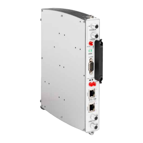
To ensure the correct use and installation of the headend, it is necessary to read the user and troubleshooting procedure manuals corresponding to the complete solution and to each of the individual modules. IKUSI reserves the right to modify the contents of this manual without prior warning. General description STC-100... -
Page 7: General Use Of The Headend
Introduction/General use of the headend CFP-700 (Ref. 4401): power supply +12 V/+24 V for selection of polarisation. EN EN BAS-900 (Ref. 4411): base-support with capacity for 9 modules (dimensions: 563x257x24 mm). MS-0504 (Ref. 1023): stand-alone multiswitch (4 SAT inputs and 4 outputs). NoTE Please read the detailed information in the manuals for the modules included in their respective packaging. -
Page 8: Basic Installation And Configuration
Attach the modules to the base one by one following the instructions given in the manuals for each module. NoTE IKUSI recommends the modules are assembled in the order shown in the above figure: Right: CFP-700/CFP-507 power supplies. Left: STC-100 transmodulators... -
Page 9: Description Of The User Interface
Basic installation and configuration/Description of the user interface Last STC-100 on the right: Master STC-100 with the DVB-T output signal. Connect the input and output signal connections in accordance with the instructions for the module manuals and the diagram shown in the previous figure. Distribute the headend power supply as symmetrically as possible (see example in above figure). -
Page 10: Ikunet Bus Configuration
Basic installation and configuration/IKUNET bus configuration IKUNET bus configuration The IKUNET bus is an Ethernet communication bus between the headend modules. The IKUNET bus is installed using Ethernet pigtails supplied with the modules. If n is the number of station modules, n-1 Ethernet pigtails are required. Definition of the master module NoTE Remember the PC configuration prior to the connection with the IKUNET... - Page 11 Enter the name of the module in the modUle name field. NoTE IKUSI recommends you give a description to the module according to its position in the headend in order to identify the modules logically and physically. For...
- Page 12 IP address for the master module of the headend, but be out of its range. The address recommended by IKUSI for the default configuration of the master module is 192.168.1.2.
- Page 13 Basic installation and configuration/IKUNET bus configuration In the home page of the selected module, enter the word “Admin” in the paSSword field. Click on aCCept. The main screen of the master module user interface is accessed through the headend > ConfigUration >...
-
Page 14: Configuration Of General Parameters
Basic installation and configuration/Configuration of general parameters NoTE To identify a module, in the liSt of headend modUleS table click on the cell corresponding to the MAC address of the module. The cell will change to a fluo- rescent green colour and the SynC and StatUS control LEDs for the selected module flash together. -
Page 15: Module Configuration
Basic installation and configuration/Module configuration ikUnet network: maC addreSS: shows the number which identifies the unit for network connection. ip addreSS: shows the number of the IP address. network maSk: shows the network mask code. defaUlt gateway: shows the Gateway IP address. - Page 16 Basic installation and configuration/Module configuration NoTE To start the headend configuration, first define the master module and the identi- fication of the slave modules for the headend, as described in the section Basic installation and configuration. liSt of headend modUleS: magnifying glaSS iCon ( ): click on the icon to access the module con- figuration.
- Page 17 Next open the dropdown menu lnb / mUltiSwitCh: Satellite: name of the input signal to the multiswitch for identification in Ì subsequent configurations: IKUSI recommends you identify the type of satellite, polarity and the bandwidth of the signal. mUltiSwitCh poSition: notifies of the multiswitch input being described.
- Page 18 Basic installation and configuration/Module configuration output configuration This permits the modification of the operating parameters for the master STC module output. To enter from headend > headend modUle liSt, click on the magnifying glass icon of the master module. Go to SettingS > oUtpUt. parameterS: freqUenCy (mhz): permits the value of the output frequency to be modified.
- Page 19 Basic installation and configuration/Module configuration mpe feC dvb-h: click on the dropdown menu to activate or deactivate the error correction protocol: This permits errors in the DVB-H transmission to be detected and corrected. timeSliCing dvb-h: click on the dropdown menu to activate or deactivate the timeslicing.
-
Page 20: Service Management
Basic installation and configuration/Service Management Service Management Selection of input services To define the services to be emitted through the output of the DVB-T output signal, go to ServiCeS > ServiCe management. In the upper side of the headend ServiCe management window there is a table showing the services available in the input, differentiated by modules. - Page 21 Basic installation and configuration/Service Management Management of output services LCN. Logic Control Number emitted by the DVB-T output signal of the headend. Deletion of the output service. Yellow cell = LCN free. Lock open: service processing not encrypted. Monitoring of bandwidth of available output Lock closed: service encrypted.
- Page 22 Basic installation and configuration/Service Management min. nUll: minimum percentage of empty packets performed. Ì aCt. nUll: percentage of actual empty packets. Ì max. nUll: maximum percentage of empty packets performed. Ì The bitrate column in the above tables inpUt ServiCeS and oUtpUt ServiCeS provides information on the individual data transfer speed for each service.
-
Page 23: Advanced Functions
Advanced functions/Save/Restore Function Advanced functions This section describes the additional functions of the user interface. NoTE The word “Live” appears in a red rectangle in the upper right corner of the main screen. This means that the headend is checking evaluation data. NoTE In local configuration there are contents which are also displayed in headend >... -
Page 24: Network Functions
Advanced functions/Network functions primary dnS Server: to use a DNS server, enter the IP address of the primary DNS server provided by the domain supplier. SeCondary dnS Server: to use a secondary DNS server, enter the IP address of the secondary DNS server provided by the domain supplier. modify with: network: click on the button to save the changes. -
Page 25: Advanced Global Transport Processing
Advanced functions/Advanced global transport processing Advanced global transport processing Enables the configuration of all the additional func- tions of the modules, the network and the services. To access from the main menu, click on ServiCeS > ServiCe management. In the main network tab the advanced operat- ing of the network can be edited, and services not included in the input can be selected or blocked. -
Page 26: Reports
Advanced functions/Reports advanCed modUle ConfigUration: click on See modUleS to open the dropdown menu. This function permits the management of the non-referenced PID for each module which are not listed in any table, and may be unblocked. NoTE In an STC module, by default no output service is selected and the required output services must be selected one by one. - Page 27 Advanced functions/Reports General report Located in the menu maSter modUle > gen- eral report. Contains all the information regard- ing the general parameters of the headend: identifiCation: general identification pa- rameters for the headend. network: network parameter information. SettingS: operational parameters for input, output, LNB / Multiswitch, LNB.
- Page 28 Advanced functions/Reports Show inpUtS: click on the second dropdown menu to select the filter by process state option. apply filterS: click on the button to start the filter process.
- Page 29 Advanced functions/Reports Unit recycling RECYCLING of ELECTRICAL AND ELECTRoNIC EqUIPmENT (Applicable in the European Union and in European countries with selective waste collection systems.) This symbol on your unit or its packaging indicates that this product cannot be treated as general domestic waste and must be handed in at the corresponding point of collection for electric and electronic equipment.
-
Page 30: Ce Certificate
CE Certificate/STC-201 CE Certificate By reproducing the CE marking, IKUSI guarantees unit compliance with the corresponding harmonised standards. STC-201 EC-Declaration of Conformity marking We, Manufacturer IKUSI, Angel Iglesias, S.A. Paseo Miramón, 170 E-20009 San Sebastián, Spain declare that the product... - Page 32 Ángel Iglesias, S.A. Paseo Miramón, 170 20009 San Sebastián, Spain Tel. +34 943 44 88 00 Fax +34 943 44 88 20 ikusi@ikusi.com www.ikusi.com 120,127a...
Need help?
Do you have a question about the STC 100 and is the answer not in the manual?
Questions and answers