Advertisement
Quick Links
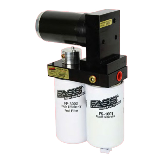
INSTALLATION MANUAL
APPLICATION:
TS-F14-125G
(125GPH @
70-75PSI)
Note: Cab and Chassis
may require modifications
TITANIUM SIGNATURE SERIES
ALL 1 / 2" FUEL PORTS
FASS DIESEL FUEL SYSTEMS® / ENGINEERED EXCELLENCE
Manufacture Date:
Powerstroke 7.3L
*Bypassing the Factory Lift Pump*
1999-2003
Powerstroke 6.0L
*Bypassing the Factory Lift Pump*
2003-2007
Standard Pickup Truck
LIFETIME
WARRANTY
AVAILABLE
Advertisement

Summary of Contents for Fass TS-F14-125G
- Page 1 Powerstroke 7.3L *Bypassing the Factory Lift Pump* APPLICATION: 1999-2003 TS-F14-125G Powerstroke 6.0L (125GPH @ *Bypassing the Factory Lift Pump* 70-75PSI) 2003-2007 Standard Pickup Truck LIFETIME WARRANTY AVAILABLE Note: Cab and Chassis may require modifications FASS DIESEL FUEL SYSTEMS® / ENGINEERED EXCELLENCE...
- Page 2 In order to qualify for the Lifetime extended warranty, your product registration form and proof of purchase from an authorized dealer must be submitted to FASS Fuel Systems within 30 days of purchase. Failure to comply will void the warranty. We have the right to deny any warranty believed to be false, altered or purchased through an unauthorized or terminated dealer.
- Page 3 -if in doubt check http://fassride.com/locate.php. (If your purchase was made on Amazon.com or Jet.com, the warranty is void. Return the FASS product to the seller and get a refund). 2. It is registered within thirty (30) days of purchase. Other conditions may apply, please see full warranty information.
- Page 4 INSTALLATION OF YOUR NEW TITANIUM FUEL SYSTEM ATTENTION: Be sure to identify the proper FASS System and fuel line configuration. For help, our product finder can be found at www.FASSride.com. Follow the instructions to see fuel line detail. Pay close attention to ALL WARNINGS...
- Page 5 NOTE: Because of the higher fuel flow these systems have to offer, you may encounter problems with the stock fuel module. FASS can solve this issue with a Suction Tube Kit. 1. Read all instructions before starting installation of this product! 2.
- Page 6 “T” Fuel Inlet Electric Heater Port “G” Fuel Port “H” Coolant Heater Front View INSTALLATION GUIDE: Step 1. Install Electrical Harness Step 2. Prep the FASS Step 3. Mount the FASS Step 4. Fuel Line Supply Step 5. Review Installation Rear View...
- Page 7 www.fassride.com TITANIUM (866) 769.3747 SIGNATURE SERIES 125 GPH 70-75 PSI (Ap proximately) Note: Going over 100 PSI WILL void warranty. NOTE: WARRANTY MAY BE VOID IF SILICONE BAND IS REMOVED FROM MOTOR!! The silicone band is in place to retain motor wires, preventing damage to the electric motor.
- Page 8 www.fassride.com (866) 769.3747 CONTENTS NOTE: Owner’s Manual available for download on our website, www.FASSride.com PFB-2001C MP-9045 FL-1058x3' WH-1005-2 FL-1002x14' PFB-2002 PBR-2001...
- Page 9 www.fassride.com (866) 769.3747 MOUNTING PACKAGE CONTENTS TWO(2) PL-1005 10-302 BHF-1002 TWO(2) RING TERMINAL PL-1010 PLB-1238 OR-223 TWO(2) PLB-12516 10-300 PL-1004 1/2" WASHERS BHN-1001 HEX BOLT 1/2" PL-1058 -20x 1 3/4" FOUR(4) HEX BOLT 3/8" WE-1001 BUTT SPLICE CABLE TIES -16x 1 1/2" FOUR(4) 3/8"...
- Page 10 www.fassride.com (866) 769.3747 MOUNTING PACKAGE CONTENTS ST-1005Px16" RS-2001 RS-2002 RS-2001C DIELECTRIC GREASE TWO (2) OR-030 OR-017 NOTE: THESE SPARE BASE O-RINGS ARE INCLUDED WITH THE KIT IN THE EVENT OF A PINCHED O-RING DURING ASSEMBLY...
- Page 11 www.fassride.com (866) 769.3747 STEP 1: INSTALL ELECTRICAL HARNESS The installation of the electrical harness is done first, allowing power to be applied to the pump for lubrication purposes later in the installation. NOTE: USE SUPPLIED DIELECTRIC GREASE SPARINGLY ON ALL ELECTRICAL CONNECTIONS!
- Page 12 www.fassride.com (866) 769.3747 STEP 1: INSTALL ELECTRICAL HARNESS The installation of the electrical harness is done first, allowing power to be applied to the pump for lubrication purposes later in the installation. A. Using ring terminals, attach red wire of the WH-1005-2 to the positive battery terminal. Attach green wire to a clean ground, preferably the negative battery terminal.
- Page 13 www.fassride.com (866) 769.3747 STEP 2: PREPARE SUCTION & RETURN LINES Some of the photo’s are of a different application, procedures are the same. Before tank is removed or moved, identify ALL areas of clearance between the tank and the truck’s bed for the best location to install the BHF assembly. With proper clearance, you want to install it as close to the Fuel sending unit as possible.
- Page 14 www.fassride.com (866) 769.3747 STEP 2: PREPARE SUCTION & RETURN LINES F. Clean the fuel module area then remove the lock ring on the top of the fuel tank. G. Once the lock ring is removed, carefully remove pick up module from fuel tank without bending fuel level arm.
- Page 15 www.fassride.com STEP 2: (866) 769.3747 PREPARE SUCTION & RETURN LINES VERY IMPORTANT: Support fuel tank on both ends allowing the natural formation of the tank to take place. Failure to perform this step can and will create an issue with less usable fuel! FUEL TANK SUPPORTS L.
- Page 16 www.fassride.com STEP 2: (866) 769.3747 PREPARE SUCTION & RETURN LINES O. Push one end of 1/2”fuel line onto ‘R’ port of suction tube assy. & one end of the 5/8”onto the ‘S’ port. Loop fuel line over frame. Do not cut at this time. Reinstall fuel tank making sure to reconnect factory suction line, factory return line, and electrical connections.
- Page 17 NOTE: Always use our dimension O-Ring for water separator, not doing this could lead to priming issues. Install 10-300 into the "E" port and 10-302 into the "T" port of the FASS, torque to 20 ft./lbs. ***FITTINGS COME EQUIPPED WITH THREAD SEALANT, DO NOT USE THREAD TAPE***...
- Page 18 www.fassride.com (866) 769.3747 STEP 3: MOUNT FUEL SYSTEM C. Assemble PFB-2002 and RS-2001C RS will make contact with bed channel when assembled correctly. Insert the PFB-2002 assembly in to bed channel align the nut with the opening on the channel. D.
- Page 19 MOUNT FUEL SYSTEM 1999-2003 WITH 7.3L POWERSTROKE E. Route FASS wire harness/wire extension along the frame rail to factory lift pump. Remove the power lead from the factory lift pump. Be sure to finish connecting wire harness before mounting into position.
- Page 20 www.fassride.com (866) 769.3747 STEP 3: MOUNT FUEL SYSTEM F. Cut off the power lead from the factory plug. Using appropriate tools, crimp the Butt Splice to the factory power lead and the WE-1001. Shrink blue cover with an appropriate heat source. G.
- Page 21 STEP 3: MOUNT FUEL SYSTEM Assemble the FASS pump bracket PBR-2001 using the RS-2002 spacer between PFB-2002 and PBR-2001 bracket with 4-3/8 bolts, nuts, and washers. Note: Torque bolts not flange nut. J. Once secure use 3-1 3/4 bolts and 3-WA-1001D spacers to mount the pump to the bracket.
- Page 22 STEP 3: (866) 769.3747 MOUNT FUEL SYSTEM NOTE: If fuel pressure gauge is pulsating after FASS installation, use snubber valve (Cat Part # 7S-3795) Fuel Filter –Install FF-3003 on side of pump with draw tube in the middle of the filter nipple.
- Page 23 Push-Lok fittings B. Route fuel line from the ‘R’ port of the suction tube assy. to the ‘R’ port on the FASS system with a gentle bend. Cut and insert PL-1005 using oil. Attach fitting to the ‘R’ port. Do not use any sealant. Torque to 18 ft./lbs.
- Page 24 7.3L does not require any modification. F. Route the fuel line from the “E” port of the FASS to the factory lift pump’s quick disconnect and cut to length. Insert the PLB-12516 into FASS fuel line using oil. Slide the PLB-12516 into the factory quick disconnect until you hear a click.
- Page 25 G. Route the fuel line from the “E” port of the FASS to the factory lift pump’s outlet quick disconnect and cut to length. Insert the PLB-1238 into FASS fuel line using oil. Slide the PLB-1238 into the facto-ry quick disconnect until you hear a click.
-
Page 26: Start The Engine
Reconnect the battery. 4. Has the system been primed? a. Turn key to the ignition position, turning on the FASS pump for 15 sec.. b. Crank engine and allow to run for at least 1 minute. 5. Check for leaks. - Page 27 To assist with priming your FASS pump crack the FF-3003. Put power to the FASS pump to activate the pump. When the tone of the pump changes you can tighten up the fuel filter. If you need a video of the priming process go to www.FASSride.com.
- Page 28 WARRANTY Disclaimer: To help insure you receive the proper system and customer support at the local level, FASS has a VIP and Authorized Dealer network representing FASS products. This is one reason you must purchase through a dealer to comply with our warranty policies. If you do not, there is no warranty! We recommend you go to www.FASSride.com, click “Find a Dealer”, put in their ZIP code, select the type of...
Need help?
Do you have a question about the TS-F14-125G and is the answer not in the manual?
Questions and answers