
Related Manuals for ClimaCool UCW 30


Summary of Contents for ClimaCool UCW 30
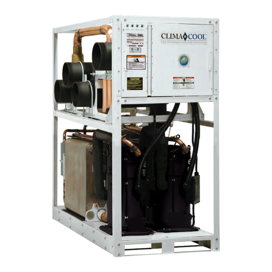
- Page 1 Water Cooled Ultimate Chiller Solution Model UCW/H 30, 50, 70, 85 Installation, Operation & Maintenance Manual ®...
-
Page 2: Table Of Contents
Table of Contents Introduction . . . . . . . . . . . . . . . . . . . . . . . . . . . . . . . . . . . . . . . . . 1 Pre-Startup Check List . -
Page 3: Introduction
Introduction General Description CAUTION/ATTENTION ClimaCool’s dedication to energy and environmental Excessive Chlorine, Chlore excessive, solides non undissolved solids and other dissous et les autres impropre leadership led to the Ultimate Chiller Solution design . improper water conditions conditions de l’eau, WILL DAMAGE the internal ENDOMMAGERA l’échangeur... -
Page 4: Pre-Installation
ClimaCool module’s warranty. A factory authorized technician is required to perform the startup of your ClimaCool chiller . Please contact the ClimaCool Customer Service Department at 405-815-3000 or technicalsupport@climacoolcorp .com to schedule . There is a minimum of three (3) weeks notice required to schedule your factory startup. -
Page 5: Physical Data
Physical Data Model UCW/H Module and Compressor Model UCW/H Module and Compressor 31.7 51.5 67.2 82.8 Capacity (tons) ¹ 31.7 51.5 67.2 82.8 Capacity (tons) ¹ 0.738 0.746 0.744 0.740 kW/Ton 0.738 0.746 0.744 0.740 kW/Ton 16.3 16.1 16.1 16.2 Full-Load EER 16.3 16.1... -
Page 6: Dimensional Data And Drawings
Dimensional Data and Drawings ® www.climacoolcorp.com... -
Page 7: Rigging And Lifting Procedures
Rigging and Lifting Procedures Rigging Each module should be lifted using lift straps threaded through the steel base cutouts and a spreader bar . Note: If no spreader bar is used, damage to the module may occur. Figure 1 Figure 2 Figure 1 Figure 2 Lifting Strap... -
Page 8: Mounting Rail And Vibration Isolation
Mounting Rail and Vibration Isolation ClimaCool recommends locking down the chiller to a concrete base or to three (3) 4” base mounting rails using the six (6) bolt holes provided in each base pan . Use bolts with a maximum diameter < 0 .6”; length to be dependent on customer mechanical layout . -
Page 9: Mounting Holes Locations
Mounting Holes The six mounting hole locations are circled in red . Dimensions are shown in inches . Top View of UC*030, 050, and 700 Base Pan Shown — Front of Unit 33.675 Top View of UC*085 Base Pan Shown —Front of Unit 33.675 ®... -
Page 10: Recommended Service Clearances
Recommended Service Clearances Top View 30” 30” Rear Service Access Front Service Access 12” 36” 36” CoolLogic Control Panel (Wall Mounted) Notes: 1 . Allow 36" clearance for electrical panels and 30" clearance for rear service access to modules . 2 . -
Page 11: Model Key
Model Key ® www.climacoolcorp.com... -
Page 12: Unit Installation
Header bank end cap kit containing four (4) grooved couplings with gaskets and four (4) end caps ClimaCool modular chillers must be installed in a conditioned and dehumidified space. The minimum foundation Field installing the mounting hardware kit will assist with... - Page 13 Unit Installation Figure 7: Header Insulation • UCW/H chillers should have couplings installed on headers 1, 4 from the top and 2, 3 from the back of the unit . Figure 9 - UCW/H Side View Sound Attenuation Panels and Gasket Attenuation panels are enclosures made of 18 gauge galvanized steel with powder coat paint finish and fiberglass insulation.
- Page 14 Unit Installation • Open the coupling by completely removing one bolt and nut (see Figure 12). • Back the other nut off as far as possible while still keep- ing the coupling intact . • Install with the nuts facing up for fastening . •...
-
Page 15: Electrical Connection
. conducteurs. ClimaCool recommends the use of a phase sequence WARNING/AVERTISSEMENT indicating instrument following the manufactures Disconnect power supply Debrancher avant d’entre- directions . An alternative is to “bump test” the compressors (ies) before servicing. -
Page 16: Voltage/Phase Monitor Wiring
Voltage/Phase Monitor Wiring ® www.climacoolcorp.com... -
Page 17: Water Piping
Water Piping Configurations on page 16 and be in place at all times when the chiller(s) is/are in operation. ClimaCool’s warranty does not cover and does not apply to Figure 15 - Flow Sensors (DPT) products which have defects or damages due to freezing... - Page 18 . This is to avoid short cycling of compressors in the chiller/heater system as well as prevent nuisance alarms . ClimaCool offers two types of water header bypass kits, direct return (Figure 16) and reverse return (Figure 17). The bypass kits must be installed on each water source loop and controls are integrated with the CoolLogic software .
-
Page 19: Water Piping Configurations
Notes: 1 . Figures 19 and 20 are required piping for proper water regulation and distribution through ClimaCool modular chillers . 2. Module order and incoming/outgoing water flow as shown in both Figure 19 and 20 can be set up as either a left-to-right or right-to-left configuration. -
Page 20: Hydronic Refrigeration
Heat Exchanger Isolation Ball Valve (2, 2-1/2 or 3”) Sensor Well (internal) Note: Figure 21 and 22 depict hydronic piping in each ClimaCool chiller module and are shown with water isolation valves . Cap Tube to Low Limit Protection Thermostat Heat Exchanger Figures 1 and 2 depict hydronic piping in each ClimaCool chiller module. -
Page 21: Part-Load Performance Advantage
Part-Load Performance Advantage Figure 23 ® www.climacoolcorp.com... -
Page 22: Filling The Water System
Filling the Water System Cleaning the System It is imperative that the water systems are free from debris prior to initial operation . See Water Treatment for a The following method is recommended to properly clean comprehensive list of precautions on page 20 . the water systems: Filling, Purging and Leak Testing the System Before cleaning the system, install a temporary... -
Page 23: Water Treatment
Table 1 . The materials exposed to the water are type 316 stainless steel, pure copper and carbon steel . Other materials may exist external to the ClimaCool chiller . It is the user’s responsibility to ensure these materials are compatible with the treated water . -
Page 24: Water Temperature Requirements
Water Temperature Requirements Condenser Water Temperature Chilled Water Temperature The condensers are designed to operate most efficiently Modules are designed for a leaving water temperature at lower entering water temperatures for lower power range from 40°F to 62°F . All cataloged modules can operate consumption . -
Page 25: Condenser & Evaporator Water Pressure Drop Charts
Condenser and Evaporator Water Pressure Drop Charts - 030, 050, 070, 085 Condenser Water Pressure Drop 30, 50, 70 & 85-Ton, UCW/UCH Series Model# UCW/UCH030 Model# UCW/UCH050 Model# UCW/UCH070 Model# UCW/UCH085 43 3 43.3 34.7 26.0 21.7 19.5 17.3 15.5 10.8 0.87 0.43... -
Page 26: Glycol Performance Adjustment Factors Charts
Glycol Performance Adjustment Factors Charts Note: Correction factors shown above are to be applied to Std. Product Data @ ARI 550/590 44°F. Leaving Chilled Water / 85°F Entering / 95°F Leaving Conditioned Water. Note: Correction factors shown above are to be applied to Std. Product Data chiller pressure drop curves for straight water. - Page 27 Glycol Performance Adjustment Factors Charts Glycol Solution Freezing Point Table 2 - Performance Adjustment Factors vs. Altitude vs. Chiller Temperature Drop Chiller Sea Level 2000 H. 4000 H. 6000 H. Water Temp. Capacity Flow gpm kW Power Capacity Flow gpm kW Power Capacity Flow gpm kW Power Capacity Flow gpm kW Power °F Mul5plier Mul5plier...
-
Page 28: Pre-Startup
Pre-Startup Water System All startups must be performed by ClimaCool factory trained personnel. Prior to chiller startup, there are certain Confirm that leak testing has been carried out. essential checks which must be completed . Failure to carry Confirm that the system is clean. -
Page 29: Pre-Startup Check List
*This form must be completed and submitted to ClimaCool Corp. a minimum of three (3) weeks prior to final scheduling of any startup. Note: If any of the above items are not complete at time of startup, back charges will be assessed for additional costs. -
Page 30: Startup
Startup All startups must be performed by ClimaCool factory 10 . Confirm the jumper locations for all master controller trained personnel. and module controllers as shown on the wiring diagrams provided on the inside electrical door panels . Review all items are complete from the Pre-Startup •... -
Page 31: Startup
Startup 18 . Verify proper communications from each module back (typically 44 leaving chilled water temperature) . If to the master controller using the “STATUS” menu, then superheat is low, this may indicate that the expansion valve indexing down to the desired compressor data screen . is overfeeding . -
Page 32: Superheat & Subcooling Flowchart
All startup paperwork and documentation must be per instructions included with the bottles . Ship the bottles submitted to ClimaCool . Future warranty claims cannot immediately to the appropriate water testing laboratory per be processed without a completed Startup and Warranty the instructions . -
Page 33: Startup And Warranty Form
Startup and Warranty Registration Form (Water-Cooled UCW/H) Sign, date and E-mail to: technicalsupport@climacoolcorp.com or Ambient Page Fax: 405.815.3052 Attn: Technical Support Temp: 1 of 1 Project Name: Contractor Name: Address: Address: City/State/Zip: City/State/Zip: Start-up Date: Phone No.: Module Compressor Model No.: Model No.: Serial No.: Serial No. -
Page 34: Chiller Operation And Maintenance
Entering Temperature Temperature • Back flush all heat exchangers. If fouling is Condenser Water Source Water Leaving Chilled Water suspected use only ClimaCool recommended Temperature Leaving Temperature Pressure Drop de-scalers (See Chemical Clean In Place Washing on Chilled Water Source Water Condenser Water page 32) . -
Page 35: Heat Exchangers
Heat Exchangers Draining “soak” for a time and then pumped again . Upon successful When performing standard maintenance procedures cleaning of a module, proceed to isolate a second module such as flushing a heat exchanger, it will be necessary to separately from the bank to repeat the cleaning process . -
Page 36: Cleaning Arrangment
Service Port (3/4") Connect to City Water Cleaning Arrangement To Cooling Tower Header Refrigerant Circuit Figure 1 - City Water Cleaning Arrangement Pete's Ports Figure 25 - City Water Cleaning Arrangement Isolation Ball Valves (2, 2 ½ or 3") Header Service Port (3/4") Refrigerant Circuit Connect to City Water... -
Page 37: Operational Limitations
Operational Limitations Voltage Limitations The following voltage limitations are absolute and operation beyond these limitations may cause serious damage to the compressor. Nominal Voltage Minimum Voltage Maximum Voltage 208/230/3/60 460/3/60 575/3/60 Water Flow Data UCW/H 030 UCW/H 050 UCW/H 070 UCW/H 085 Minimum Evaporator Water Flow (gpm) Maximum Evaporator Water Flow (gpm) Minimum Condenser Water Flow (gpm) -
Page 38: Compressor Information
Compressor Information Model UCW/H uses scroll compressors which are highly compressor while it is operating to observe valid oil sight efficient and extremely reliable. The information contained glass levels . Oil is pressure-injected either into a gauge in this manual will be useful for their care . connection on the suction line or injected into the oil process port at the bottom of the compressor housing . -
Page 39: Refrigeration Circuit Diagram
SUCTION PRESSURE TRANSDUCER WAT ER COOLED TITLE REFRIGERATION CIRCUIT DIAGRAM UCW/H WATER COOLED SCROLL CHILLER DESCRIPTION (REFRIGERANT CIRCUIT #1 OF 2 SHOWN SIZE REVISED DWG NO ClimaCool Corp. CCE-08001-2.VSD CCE-08001-2.VSD APPROVED DATE FILENAME SCALE DRAWN BY DATE SHEET 1 OF 1 CCE-08001-2.vsd... - Page 40 SUCTION PRESSURE TRANSDUCER WATER COOLED TITLE REFRIGERATION CIRCUIT DIAGRAM UCH WATER COOLED SCROLL HEAT PUMP CHILLER DESCRIPTION (REFRIGERANT CIRCUIT #1 OF 2 SHOWN SIZE REVISED DWG NO ClimaCool Corp. CCE-09001-2.VSD CCE-09001-2.VSD APPROVED DATE FILENAME SCALE DRAWN BY DATE SHEET 1 OF 1 CCE-09001-2.vsd...
-
Page 41: Refrigeration System Re-Processing And Charging
. It is necessary to use a micron meter equipped with an absolute pressure gauge (or transducer) to take this reading . ClimaCool recommends the triple evacuation process to ensure the proper removal of moisture and contaminants from the refrigeration system . -
Page 42: Engineering Guide Specifications
Engineering Guide Specifications constructed of 300 stainless steel; designed, tested, and General UL stamped in accordance with ASME Section VIII pressure Factory-assembled and wired water cooled, water chiller . vessel code for 650 psig working refrigerant pressure on Chiller consists of two compressors, one evaporator and the condenser . -
Page 43: Engineering Guide Specifications
Engineering Guide Specifications The Master Controller shall monitor and report the following system parameters for the chiller system: • Chilled water entering and leaving temperature • Condenser water entering and leaving temperature • Evaporator and condenser water flow availability Any module failure condition shall cause a “fault” indication at the Master Control Panel and shutdown of that compressor circuit with the transfer of the load requirements to the next available compressor circuit . -
Page 44: Options And Accessories
Options and Accessories Automatic CS Series Strainer Package Pressure Differential Flow Sensor Field installed, high quality, low maintenance stainless steel Field installed to prevent operation of chiller without filtration systems with 60 or 80 mesh stainless steel screens sufficient water flow to the evaporator and/or condenser. will reduce operating costs and prevent nuisance condenser Seismic Certification issues. -
Page 45: Stainless Steel Strainer Option
Clamped Lid Models: CS strainer models 3CS and 4CS have strainer housing, lid assembly and screen for damaged “over-center latch clamp” lid designs . The over-center or missing parts . Contact ClimaCool’s customer service clamp does not require adjustment when installing or department for any replacement parts . - Page 46 Stainless Steel Strainer Option Table 3 Follow the steps below when cleaning the CS strainer Table 1 element: Recommended Strainer Bolt Size Torque Step 1. (Bolted Lid Models): Remove the top of the (ft. lbs) (inches) 5/16 - 18 60 - 80 strainer by removing the Grade 5 Zinc plated bolts 3/8 - 16 15 - 25...
- Page 47 Stainless Steel Strainer Option What is Water Hammer? Figure 29 Water hammer is a phenomenon that can occur in fluid systems with long pipes . Water hammer is a rapid change RED POINTER OUTER RING of pressure caused by a rapid change in velocity. If the flow (TIME BETWEEN has been abruptly shut off downstream, the pressure in the FLUSHES)
- Page 48 Stainless Steel Strainer Option Operation Instructions Water Resistance Flush valve line must be piped to atmospheric pressure such The valve and controller are water-resistant, but not as an open floor drain. The flush line should not undergo any water-proof . Do not install below ground level where the changes in elevation and should be sloped downward in the component can be submerged in water .
-
Page 49: Stainless Steel Strainer Option
Stainless Steel Strainer Option When the differential set point is reached both the audible and visual alarms will be triggered and will remain engaged until both the alarm condition is corrected and the alarm-reset button is pressed (if the alarm-reset button is pressed but the differential pressure is beyond the set point, the alarms will re-engage immediately) . -
Page 50: Wye Strainers
WYE Strainers Pre Installation Checklist: Installation Procedure: Ensure working conditions (pressure/temperature) are within the specified capacity of the product being Also, for maximum efficiency, install a differential installed. Please refer to the certified drawings to assist pressure gauge at inlet and outlet connections or at the in determining these values . - Page 51 WYE Strainers Start-Up Procedure Screen Removal/Cleaning/Replacement Isolate the strainer by closing the inlet and outlet valve To remove all fluid from the strainer belly, a drip-leg can connections on either side of the WYE strainer . Make be installed or the piping can be placed at a 1/4” slope. sure valves are bubble tight .
-
Page 52: Basket Strainers
Basket Strainers The correct size of Basket Strainer is determined by its job 4. Install a standard ANSI (1/8” thick) flange gasket function, not by the size of the pipeline . between the basket strainer and pipeline flanges, on both sides. Install lubricated flange bolts and hand tighten . - Page 53 Basket Strainers Maintenance 6. Remove any debris or sludge from within the basket strainer . Basket strainers require little monitoring once they are Replace clean basket into its original position, enrusing properly installed. The pressure differential across the it is squarely positioned on the screen seat . strainer should be checked periodically to determine if the 8.
-
Page 54: Electrical Data
Electrical Data UCW ® www.climacoolcorp.com... -
Page 55: Electrical Data
Electrical Data UCH ® www.climacoolcorp.com... -
Page 56: Power Distribution Drawing
Notes: Breaker panel represents field power supply and is to be installed by others. Not provided as part of the ClimaCool modular chiller system . Breaker panels can be supplied for skid mount pump/tank packages or new construction projects as options . Consult your local ClimaCool Representative . -
Page 57: Wiring Diagrams
Wiring Diagrams - 030, 050, 070 - Cooling Only ® www.climacoolcorp.com... - Page 58 Wiring Diagrams - 030, 050, 070 - Cooling Only ® www.climacoolcorp.com...
- Page 59 Wiring Diagrams - 030, 050, 070 - Heat Pump ® www.climacoolcorp.com...
- Page 60 Wiring Diagrams - 030, 050, 070 - Heat Pump ® www.climacoolcorp.com...
- Page 61 Wiring Diagrams - 085 - Cooling Only ® www.climacoolcorp.com...
- Page 62 Wiring Diagrams - 085 - Cooling Only ® www.climacoolcorp.com...
- Page 63 Wiring Diagrams - 085 Heat Pump ® www.climacoolcorp.com...
- Page 64 Wiring Diagrams - 085 Heat Pump ® www.climacoolcorp.com...
- Page 65 Wiring Diagrams - Master Panel ® www.climacoolcorp.com...
-
Page 66: Wiring Diagrams
Wiring Diagrams - Master Panel ® www.climacoolcorp.com... -
Page 67: Troubleshooting Guide
Troubleshooting Guide disconnect all electrical power including remote disconnects WARNING! before servicing . Follow proper lockout/tagout procedures . The troubleshooting guidelines recommended in this section Only a qualified licensed electrician or persons trained to could result in exposure to electrical safety hazards . Please handle live electrical components should be allowed to work refer to the safety warnings provided in this manual . -
Page 68: Troubleshooting Guide
Replace high pressure switch. Causes and Prevention of Freeze-Ups Possible Cause Remedy Improper charging Charge per ClimaCool data plate information, located on the chiller, following the Superheat and Subcooling procedure described in IOM (page 25). page 29 Improper chilled water circulation Use an ample sized cleanable strainer in the chilled water circuit;... -
Page 69: Warranty Certificate
Warranty Certificate ® www.climacoolcorp.com... - Page 70 Notes ® www.climacoolcorp.com...
- Page 71 Notes ® www.climacoolcorp.com...
- Page 72 ClimaCool works continually to improve its products. As a result, the design and specifications of each product at the time for order may be changed without notice and may not be as described herein . Please contact ClimaCool’s Customer Service Department at 405-815-3000 for specific information on the current design and specifications. Statements and other information contained herein are not express warranties and do not form the basis of any bargain between the parties, but are merely ClimaCool’s opinion or commendation of its products .
Need help?
Do you have a question about the UCW 30 and is the answer not in the manual?
Questions and answers