Yazaki Aroace WFC-SC10 Installation Instructions Manual
Water fired single-effect
absorption chiller and chiller-heater
Hide thumbs
Also See for Aroace WFC-SC10:
- Installation instructions manual (24 pages) ,
- Installation manual (21 pages)
Table of Contents
Advertisement
Quick Links
Download this manual
See also:
Installation Manual
INSTALLATION INSTRUCTIONS
WATER FIRED SINGLE-EFFECT
ABSORPTION CHILLER AND CHILLER-HEATER
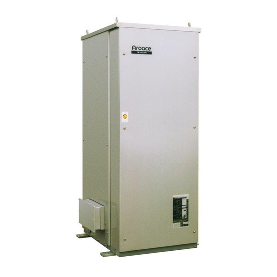
This product is a water fired absorption unit which provides chilled water for cooling or hot water
for heating in central plant type air conditioning systems. Units with nominal refrigeration
capacities of 10, 20, and 30 tons are complete with operating and safety controls. The absorp-
tion chiller or chiller-heater is energized by heat medium (hot water) at 158
process, cogeneration, solar or other waste heat source.
•
•
•
•
•
•
•
•
INSTALLATION
V I
•
WFC-SC10, 20, 30
WFC-SH10, 20, 30
CONTENTS
Page
2
UNIT NAMEPLATE
•
3
•
3
•
3
F
O
U
N
D
•
3
•
4
P
P I
N I
G
•
6
•
8
•
•
1
0
F to 203
o
A
I T
O
N
F from a
o
Page
10
1
0
1
0
1
2
1
2
1
2
1
5
24
24
Advertisement
Table of Contents

Subscribe to Our Youtube Channel
Related Manuals for Yazaki Aroace WFC-SC10


Summary of Contents for Yazaki Aroace WFC-SC10
-
Page 1: Table Of Contents
WFC-SC10, 20, 30 WFC-SH10, 20, 30 INSTALLATION INSTRUCTIONS WATER FIRED SINGLE-EFFECT ABSORPTION CHILLER AND CHILLER-HEATER This product is a water fired absorption unit which provides chilled water for cooling or hot water for heating in central plant type air conditioning systems. Units with nominal refrigeration capacities of 10, 20, and 30 tons are complete with operating and safety controls. -
Page 2: General
After the equipment has been installed an unit, must be observed to ensure the safety of Authorized Yazaki Service Provider will check the personnel and warranty validation. installation and supervise the initial start-up and Each absorption chiller and chiller-heater has operation of the absorption unit. -
Page 3: Physical Data
Standard Standard Specifications. The Authorized Yazaki factory setpoints are adjustable from 59.9 F to Service Provider can adjust the setpoints with 41.9 F (leaving chilled water) and 122.9... -
Page 4: Equipment Dimensions
EQUIPMENT DIMENSIONS WFC-SC10/SH10 4 Eye Bolts For Lifting Field Wiring Junction Box Mounting Plate 26.4 29.9 33.1 Heat Medium Outlet Cooling Water 1-1/2 NPT Outlet 2 NPT 22.8 Heat Medium Inlet 1-1/2 NPT Chilled/Hot Water Outlet Cooling Water 1-1/2 NPT Inlet 2 NPT Chilled/Hot Water Inlet 1-1/2 NPT... - Page 5 EQUIPMENT DIMENSIONS WFC-SC30/SH30 11.7 Cooling Water Cooling Water Crossover (By others) Crossover (Optional) 4 Eye Bolts 4 Eye Bolts For Lifting For Lifting 49.6 Mounting Mounting Field Wiring Field Wiring Plate Plate Junction Box Junction Box 54.3 Note: Cooling Water Crossover Pipe Field Connections 57.5 Shown In ( ) Are 3"...
-
Page 6: Typical System Design
TYPICAL SYSTEM DESIGN (SINGLE MODULE) WFC-SC10/SH10 WFC-SC20/SH20 WFC-SC30/SH30... - Page 7 TYPICAL SYSTEM DESIGN (MULTIPLE MODULES) 2 X MODULES (WFC-SC20/SH20, WFC-SC30/SH30)
-
Page 8: Internal Wiring
INTERNAL WIRING JUNCTION WFC-TRUL1 208V 208V, 60Hz, 3PH POWER SUPPLY THRP CN12 JUNCTION BOX MONITORING UNIT EGBON 5 CM2 CTF CM1 P A B C D E S4 S5 S6 S7 S8 S11 S12 S13 S14 S3 S4 S5 S6 S7 S8 S11 S12 S13 S14 TR11 A B C D E F G H... - Page 9 INTERNAL WIRING OPTIONAL JUNCTION BOX CONNECTIONS SYMBOL DESCRIPTION REMARK TERMINAL DESCRIPTION REMARKS Cooling water 1, 2 (DCP) Remote monitoring temperature sensor A (C1) Cooling mode selection Remote Changeover valve SH model only B (H1) Heating mode selection selection of C (CHON) Start selection Chilled/hot water COOL, HEAT,...
- Page 10 When the absorption chiller is delivered to the job site, inspect for any transit damage. Report any damage to the carrier and note on the bill of lading. Notify the Yazaki Sales Representative or Distributor before proceeding with the installation of a damaged unit.
- Page 11 57.5 44.9 41.9 54.3 33.1 Mounting Plate 29.9 Mounting Plate WFC-SC20/SH20 WFC-SC10/SH10 WFC-SC30/SH30 FRONT FRONT 10.0 10.0 10.0 49.9 61.9 61.9 FRONT 10.0 74.3 INSTALLATION AREA MODEL DIM. (IN) 44.9 44.9 SC10/SH10 118.2 85.9 41.9 SC20/SH20 131.2 97.9 Mounting Mounting Plate Plate SC30/SH30...
- Page 12 FOUNDATION Mount the absorption chiller on a level floor or foundation capable of supporting the operating weight of the unit (refer to PHYSICAL DATA on Page 3). A concrete base, with dimensions shown in Fig. 4, should be at least 12 in. thick and Fig.
- Page 13 CAUTION 1. DO NOT EXCEED 80 - 120% OF Water Supply Chiller/Chiller - Heater STANDARD CHILLED/HOT WATER FLOW. Check/Reducing Valve 2. DO NOT EXCEED 85.3 PSI IN THE Expansion Tank CHILLED/HOT WATER CIRCUIT AT THE ABSORPTION CHILLER. Relief Valve Chilled/Hot Water Water Make-Up/ 3.
- Page 14 Note 3 Cooling Water specifications. As an alternative, install the Absorber Outlet Stop Valve optional Yazaki cooling water crossover pipe Cooling Water assemblies. Absorber Inlet 3" Cu Tube A balancing valve should be installed adjacent to the cooling water outlet on each...
- Page 15 above 120 F may damage the cooling tower fill should be drained from the chiller-heater. material at the start of cooling operation. This When the cooling water circuit is not drained problem can be prevented by overriding the but is subject to ambient temperatures below motorized 3-way valve (CWV) to bypass cooling freezing, install a heater in the cooling tower sump.
- Page 16 INTERLOCK CONTACTS (NC) Option 2: HEAT INPUT CONTROL BY HEAT MEDIUM PUMP ONLY Option 3: HEAT INPUT CONTROL BY HEAT MEDIUM BYPASS VALVE ONLY OPTIONAL COOLING WATER OPTIONAL COOLING WATER TEMPERATURE CONTROL TEMPERATURE CONTROL (With Cooling Water Valve Override) (Without Cooling Water Valve Override)
- Page 17 EXTERNAL WIRING (SINGLE MODULE) SYMBOL DESCRIPTION REMARKS Cooling water pump fused disconnect Cooling tower fan fused disconnect Supplied by others Heat medium pump fused disconnect Heat medium bypass valve fused disconnect Chilled/hot water pump motor contactor Cooling water pump CHILLER OR CHILLER-HEATER JUNCTION BOX Supplied by motor contactor others (24V...
- Page 18 EXTERNAL WIRING (SINGLE MODULE) 3. A Cooling Tower Switch (CTS), installed in SYMBOL DESCRIPTION REMARKS the cooling tower sump, controls the cooling Cooling water temp. water temperature by cycling the cooling control valve (3-way) tower fan. Cooling water temp. Supplied by 4.
- Page 19 OPTIONAL I/O BOARD CONNECTIONS TERMINAL DESCRIPTION REMARKS Additional 7, 8 Shutdown interlock interlock (ST2) (NC or NO) 9,10 Chilled/hot water Input control (IF1) freeze protection from temp. switch MG 3, 7 Heat medium (36.5°F ON, (IF3) freeze protection 39.2°F OFF) 7, 8 Chiller-heater (CHSTN) standby mode...
-
Page 20: R E C E V I N I G
DO NOT CLOSE THE DISCONNECT until ance for removal of panels and service access. approved by an Authorized Yazaki Service DO NOT attach conduit to the absorption chiller Provider. cabinet. The 1/2 in. trade size conduit entry in the... -
Page 21: Water Quality
Table 2 WATER QUALITY REQUIREMENTS INSTALLATION CHECK & REQUEST FOR START-UP After the absorption chiller or chiller-heater START-UP FORM and send to the Yazaki Sales has been installed, piped and wired as described Representative or Distributor at least 2 weeks in these instructions, but before any attempt is prior to the required start-up date. -
Page 22: Installation Check And Request For Start-Up
YAZAKI WATER FIRED CHILLER INSTALLATION CHECK AND REQUEST FOR START-UP ____________________________________________________________________ (Yazaki Service Provider) Address: ____________________________________________________________________________________ Project Name: ________________________________________________________________________________ Address: ____________________________________________________________________________________ Model No: ______________________________ Serial No: __________________________________________ The Work (as checked below) is in progress and will be completed by: __________________________________ 2. - Page 24 Fax: 469-229-5448 Email: yazaki@yazakienergy.com www.yazakienergy.com This symbol on the product’s nameplate means it is listed by UNDERWRITERS LABORATORIES, INC. Yazaki reserves the right to discontinue, or change at any time, specifications or designs without notice and without incurring obligations. IN-WFCS-0909...
Need help?
Do you have a question about the Aroace WFC-SC10 and is the answer not in the manual?
Questions and answers