Table of Contents
Advertisement
Quick Links
Advertisement
Table of Contents

Related Manuals for ASTECH LDM301-302


Summary of Contents for ASTECH LDM301-302
- Page 1 Manual LDM301-302 Firmware Version from 1.5 Version 2.0...
- Page 2 Proper care has been used in compiling this document. No liability will be accepted in the event of damage resulting from the failure to comply with the information contained herein. ASTECH GmbH, Schonenfahrerstr. 5, D-18057 Rostock Internet www.astech.de E-Mail info@astech.de Phone +49 (0)381 / 44073-0 Fax +49 (0)381 / 44073-20...
- Page 3 Revision history Manual Version Date Changes 25.06.2018 Laser divergence 18.10.2016 Laser divergence 26.02.2016 MTBF 01.06.2014 New design...
-
Page 4: Table Of Contents
Content LDM301-302 Manual Content General Information .................. 9 Safety advice .................... 11 Basic safety advice ................11 Safety advice for operating the laser ..........12 Advice for operating device ............14 Norms ..................... 16 Disposal ................... 16 Operating conditions ................17 Electrical installation conditions ............. - Page 5 LDM301-302 Manual Content Overview of commands ..............58 Transmission protocol RS-232 and RS-422 ........61 Identification ................... 61 Operation Mode ................63 Status....................65 Setup Parameter ................67 Maintenance .................... 80 Maintenance by the user ..............80 Firmware update ................80 Repair ....................
- Page 6 List of figures LDM301-302 Manual List of figures Figure 1 : Device warning sign ................. 14 Figure 2 : Position of the device warning sign ..........14 Figure 3 : Beam diagram for LDM301 with 1.7 mrad ........28 Figure 4 : Beam diagram for LDM301 with 10 mrad ........29 Figure 5 : Beam diagram for LDM302 ..............
- Page 7 LDM301-302 Manual List of tables III. List of tables Table 1 : Electrical installation conditions ............17 Table 2 : Technical data ..................22 Table 3 : Device types ..................25 Table 4 : Technical Data LDM302 ..............26 Table 5 : Beam size for LDM301 with 1.7 mrad ..........28 Table 6 : Beam size for LDM301 with 10 mrad ..........
- Page 8 List of tables LDM301-302 Manual Used Symbols Sign warns against emitting visible and invisible laser radiation. Sign warns against danger of electrical power and of electric shock. Sign warns against danger. Sign shows information for use in hazardous environments. Sign indicates important information regarding device use of the device.
-
Page 9: General Information
LDM301-302 Manual General Information General Information The laser distance measurement device LDM301 is developed for industrial applications. It enables the non-contact measurement of distances and speed with a precision down to the centimeter. The device measures with short measurement time onto any diffusely reflecting target surface also without using a reflector. - Page 10 General Information LDM301-302 Manual The device operates on the basis of time of flight measurement. Short laser pulses are transmitted. The light pulse reflected from the target is detected by the receiver. The distance can be determined by the time shift.
-
Page 11: Safety Advice
LDM301-302 Manual Safety advice Safety advice Basic safety advice Please read the safety and operating advice carefully, and observe the advice when operating the device. Danger, laser radiation Do not open the LDM30x, otherwise Laser radiation can be emitted that can cause eye injuries. Please observe all information and guidelines for operating the Laser. -
Page 12: Safety Advice For Operating The Laser
Safety advice LDM301-302 Manual Protection degree: In accordance with the Protection Degree IP67, the LDM30x is protected against jet water and dust, and against short submersion into water. When operating the device under extreme outdoor environmental conditions, the use of additional weather protection is recommended (e.g. - Page 13 LDM301-302 Manual Safety advice Safety advice for laser class 2 – Pilot Laser The pilot laser is a class 2 laser device based on the norm IEC 60825-1:2007 (Safety of laser products – Part 1: equipment classification and requirements). The Laser power is limited to maximum 1 mW. The Laser radiation is visible. A short-term exposure (duration up to 0.25 s) is harmless to the eye.
-
Page 14: Advice For Operating Device
Safety advice LDM301-302 Manual Figure 1 : Device warning sign Figure 2 : Position of the device warning sign Advice for operating device The LDM30x should not be put into operation when optical parts are fogged or dirty. The optical components of the equipment... - Page 15 LDM301-302 Manual Safety advice fluctuations. When extreme temperature fluctuations are occurring use additional protection housing. It is not allowed to operate the device in explosive environments. The device corresponds to the protection degree IP 67, and is protected against jet water and short submersion. Please observe...
-
Page 16: Norms
Safety advice LDM301-302 Manual Norms The device conforms to the following norms: IEC 61326-1:2005 Electrical equipment for measurement, control and laboratory use - EMC requirements - Part 1: General requirements (IEC 61326-1:2005); German version EN 61326-1:2006 IEC 60825-1:2007 Safety of Laser products – Part 1: equipment... -
Page 17: Operating Conditions
LDM301-302 Manual Operating conditions Operating conditions Electrical installation conditions Use only a supply voltage of 10 V ... 30 V DC (direct current voltage). For using the heating, direct current voltage of 24 V is recommended. The limit values for the input voltage have to be observed. Do not wire inputs as outputs. -
Page 18: Appropriate Use
Operating conditions LDM301-302 Manual Appropriate use The device is intended for the following applications: Distance and speed measurement and output of measured data via the interfaces RS-232, RS-422, analog output SSI or Profibus. Use of the special measurement functions ... -
Page 19: Improperly Use - Error Sources
LDM301-302 Manual Operating conditions Improperly use – error sources The device may only be used when the safety advice described in chapter 0 is observed. The non-observance of the safety advice can lead to damages of the device or to injuries of the eyes. -
Page 20: Device Description
Device description LDM301-302 Manual Device description General device description The laser distance measurement device LDM301 is intended for distance measurement onto static and moving objects with a precision down to the centimetre: Measurement in the range of 0.5 m ... 300 m onto natural surfaces with 90 % reflectivity. - Page 21 LDM301-302 Manual Device description When certain temperature thresholds are exceeded, the heating is swichted on or off automatically. Values preset in the factory: +4 °C heating is switched on and +10 °C heating is switched off. The values can be specifically configured by the user (refer to...
-
Page 22: Technical Data
Device description LDM301-302 Manual Technical Data Table 2 : Technical data Measurement properties Measurement principle Laser pulse - Time of flight measurement Measurement range onto natural surfaces 0.5 m ... 300 m onto target board 300 m ... 3000 m ... - Page 23 LDM301-302 Manual Device description Laser Pilot Laser Laser Class 2 (red visible) Wavelength 635 nm Electrical installation conditions Supply voltage 10 V ... 30 V DC Power consumption < 5 W (without heating) 11.5 W (with heating at 24 V)
- Page 24 Device description LDM301-302 Manual Interface / Connections triggering (adjustable near field suppression and window function Environmental and application conditions Operating temperature -40 °C ... +60 °C Storage temperature -40 °C ... +70 °C Air humidity 15 % ... 90 % Dimensions (LxWxH) 136 mm ×...
-
Page 25: Device Types
LDM301-302 Manual Device description Device Types The LDM301 is available in different designs and with different interfaces. The following devices are available: Table 3 : Device types Type LDM301A-RS232 LDM301A-RS422 LDM301P LDM301S Serial Interface RS-232 RS-422 RS-232 RS-232 Analog output... -
Page 26: Technical Data Ldm302
Device description LDM301-302 Manual Technical Data LDM302 The LDM302 is a special version of the LDM301. It was designed for badly reflecting surfaces due to an adapted signal processing. Both gauges use the same hardware and software basics. All the information in this manual are valid for both devices as far as there is no other statement. - Page 27 LDM301-302 Manual Device description Electrical installation conditions Supply voltage 10 V ... 30 V DC Power consumption < 5 W (without heating) 11.5 W (with heating at 24 V) Interface / Connections Interfaces 1 x 12-pole (Binder series 723) M18...
-
Page 28: Laser Divergence
Device description LDM301-302 Manual Laser divergence The LDM301 is available in two different versions with respect to the laser divergence. LDM301 with 1.7 mrad (Standard) Figure 3 : Beam diagram for LDM301 with 1.7 mrad The divergence of the laser is 1.7 mrad x 0.08 mrad (rectangle). The receiver divergence is 2.9 mrad (circle). -
Page 29: Figure 4 : Beam Diagram For Ldm301 With 10 Mrad
LDM301-302 Manual Device description LDM301 with 10 mrad (Option) Figure 4 : Beam diagram for LDM301 with 10 mrad The divergence of the laser is 7 mrad x 4 mrad (rectangle). The receiver divergence is 14.3 mrad (circle). Table 6 : Beam size for LDM301 with 10 mrad... -
Page 30: Figure 5 : Beam Diagram For Ldm302
Device description LDM301-302 Manual LDM302 with 3.7 mrad (Standard) Figure 5 : Beam diagram for LDM302 The divergence of the laser is 3.7 mrad x 3.7 mrad (square). The receiver divergence is 6.3 mrad (circle). Table 7 : Beam size for LDM302... -
Page 31: Functional Elements
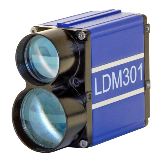
LDM301-302 Manual Device description Functional Elements The casing consists of a robust, corrosion-resistant extrusion-molded aluminum structure with a front cover plate and a back cover plate equally corrosion-resistant. On each lateral side and on the underside of the LDM 301 casing there are three support pads with mounting holes (M4) for mechanical attachment of the LDM 301 (see Figure 7). -
Page 32: Mechanical Integration Requirements
Device description LDM301-302 Manual Mechanical Integration Requirements For integration of the LDM301 Laser Distance Meter, three different versions of mechanical attachment are available. 1. Attachment to a lateral surface: For attachment to the lateral surfaces, the LDM301 provides three support pads (Figure 7) with mounting holes (M4 x 6). -
Page 33: Connector Pin Assignments
LDM301-302 Manual Device description The zero point of LDM301 corresponds to the external surface of the front cover. Connector pin assignments Depending on the implemented configuration version of the various LDM 301 models, different terminal facilities are available for connections. All models share the same type of main connector port. -
Page 34: Figure 9 : Connection Diagram Ldm301S Ssi
Device description LDM301-302 Manual Attention on cable colors: blue – VCC and gray/pink – GND! Please use only high quality shielded cable. Table 8 : Pin assignments of main connector port Color code of RS-232 RS-422 Description cable White RS-232 send data / RS-422... -
Page 35: Figure 10 : Connection Diagram Ldm301P Profibus-In
LDM301-302 Manual Device description Profibus Port of LDM301P (M12) For Profibus connection there are 3 B-encoded 5-pole M12 connectors. The connection must be made with Profibus conform cables. Figure 10 : Connection diagram LDM301P Profibus-IN Figure 11 : Connection diagram LDM301P Profibus-OUT... -
Page 36: Status Display
Device description LDM301-302 Manual Status Display Figure 12 : Status Display Table 9 : Status display - functions Function Display Status (Signal strength) Target Reflectivity No signal (0) Red blinking Very weak signal (< 600) Weak signal (600…1000) Yellow Signal available (1000 … 1500) Green Good signal (1500 …... -
Page 37: Pilot Laser
LDM301-302 Manual Device description 4.10 Pilot Laser The pilot laser (see Figure 7) is intended to support alignment to a given target point during start-up action of the LDM 301. It qualifies as a Class 2 Laser device and operates at 635 nm (red) in the visible range. The pilot laser is not aligned to emit in a direction parallel with the measurement Laser. -
Page 38: Interface Description
Interface description LDM301-302 Manual Interface description For interfacing, the LDM 301 provides different connectors depending on the type (see chapter 4.3, Device Types). A main connector port (Figure 7) is used for RS-232- or RS-422-interface and analog output and additional connectors provide SSI interface (Figure 8, no. -
Page 39: Rs-422 Interface
LDM301-302 Manual Interface description RS-422 interface Figure 15 : Wiring RS-422 to RS-422 unit The RS232 / RS422-interface of devices which are equipped with a Profibus interface should only be used for test purposes. Measurement via RS232 / RS422-interface is not recommended for these device types. -
Page 40: Q1 / Q2 - Digital Switching Output
Interface description LDM301-302 Manual Q1 / Q2 – Digital switching output The purpose of Q1 and Q2 is to represent distance readings as logic operation data. They report events of positive or negative exceeding of a preset switching range with a certain amount of hysteresis. -
Page 41: Figure 17 : Example Of Switching Output Wiring
LDM301-302 Manual Interface description Figure 17 : Example of switching output wiring ASTECH GmbH Page 41... -
Page 42: Qa - Analog Output
Interface description LDM301-302 Manual QA – Analog output The analog output enables the normed, analog transmission of distance data across large distances using a two-wire line. The current of 4 mA to 20 mA impressed in the line is proportional to the measured distance within an adjustable distance interval. -
Page 43: Figure 20 : Wiring Analog Output Qa Of Ldm301
LDM301-302 Manual Interface description Figure 20 : Wiring analog output QA of LDM301 ASTECH GmbH Page 43... -
Page 44: Trigger Port
Interface description LDM301-302 Manual Trigger Port The trigger port allows two different uses: Start a single distance measurement DF by an external signal in the form of a voltage pulse, the delay of the release trigger (trigger delay) and to triggered edge (trigger level) may be set. -
Page 45: Figure 21 : Example For The External Wiring Of The Trigger Input
LDM301-302 Manual Interface description Figure 21 : Example for the external wiring of the trigger input Figure 22 : Interconnection of several LDM301 devices ASTECH GmbH Page 45... -
Page 46: Ssi Interface Of Ldm301S
Interface description LDM301-302 Manual SSI Interface of LDM301S Specification The LDM301S is equipped with an SSI-data interface (SSI = synchronous serial interface). By the SSI master the current measurement data is collected, it sends to the clock for the shift register in the slave. The SSI slave sends its data from the shift register bit by bit to the master. -
Page 47: Profibus Interface Of Ldm301P
LDM301-302 Manual Interface description Profibus Interface of LDM301P General LDM301P supports the Encoder-Profile of the Profibus (No. 3062 of the PNO). The LDM301P is used here as a linear encoder. As part of the encoder profile, the LDM301P can work as Class1 or Class2 (recommended) encoder. All variants are implemented via the GSD file. -
Page 48: Table 10 : Profibus Baud Rate Depending On Segment Length
Interface description LDM301-302 Manual If several slaves (LDM301P) are operated on a Profibus, please connect successively and set different addresses. Bus Termination For LDM 301 operation, an external bus terminator must be installed. Voltage supply of 5 V required for the terminator is available at Profibus-OUT. This 5 V supply is electrically isolated from general voltage supply (VCC) and rated for a current load up to 100 mA. -
Page 49: Figure 24 : Profibus Connection Diagram Ldm301P M12 Connector
LDM301-302 Manual Interface description Table 11 : Profibus cable type A features Parameter Value Wave resistance 135 ... 165 Ohm Capacitance per unit length < 30 pf/m Loop resistance < 110 Ohm/km Cable wire diameter > 0.64 mm Cable wire cross-section >... -
Page 50: Table 12 : Explanation Profibus Parameters
Interface description LDM301-302 Manual Table 12 : Explanation Profibus parameters Name Description Class 2 function: Selection of the slave type according to the encoder profile. Commissioning Send more than the 6 byte standard diagnosis Diagnostics: (16 Byte as Class1 Slave, 77 Byte as Class 2 Slave) - Page 51 LDM301-302 Manual Interface description Octet Type Output bool unused bool class functionality on/off bool commissioning diagnostic on/off bool unused bool reserved for future use bool reserved for future use bool reserved for manufacturer bool reserved for manufacturer class 2 parameter 10..13...
-
Page 52: Table 14 : Profibus Diagnostic Data Length
Interface description LDM301-302 Manual Because of the LDM301P is a linear encoder for measuring absolute distances the parameters "code sequence", "scaling function control", "measuring units per revolution" and "measuring range in measuring units" are ignored. Diag Common The (general) diagnosis data correspond entirely to the profile standard, and will be updated with every Profibus-Diagnosis-Request. -
Page 53: Table 15 : Profibus Diagnostic Data
LDM301-302 Manual Interface description Table 15 : Profibus diagnostic data Octet Type Input byte diag state 1 (Profibus default) byte diag state 2 (Profibus default) byte diag state 3 (Profibus default) byte diag state 4 (Profibus default) 5..6 word slave diag... -
Page 54: Table 16 : Profibus Input
Interface description LDM301-302 Manual Cyclic data exchange – Input (Slave Master) The localization data from the LDM301P are signed. With the SF parameters (scale factor) the signs can inverted. The resolution is also determined by SF. The arrangement of the octet in the telegrams is Profibus-compliant (big endian), e.g. - Page 55 LDM301-302 Manual Interface description zyklische Berechnung von: M DataEx Laser Offset The value M is not permanently stored in LDM301P, it will get lost if Offset you disconnect the device. The offset can be written directly as a parameter Octet 32...35.
-
Page 56: Installation
Installation LDM301-302 Manual Installation Preparation Work before the installation Remove the packaging of the LDM301 Check the delivery scope for completeness Check the device and the accessories for damages Check the connections and the cables for damages... -
Page 57: Figure 25 : Program Ldmtool
LDM301-302 Manual Installation Before switching on the power supply make sure that all cable ends are protected against short circuits! Connect cable terminals as required for the particular operating mode. To prevent short circuits, seal unused cable ends! For starting-up, a PC with RS-232 or RS-422 data interface and a terminal program are required. -
Page 58: Description Of Commands
Description of commands LDM301-302 Manual Description of commands Overview of commands Table 19 : Overview of commands Command- Command Description Standard(s) Range(s) Class Operation Single distance measurement Mode Continuous distance measurement Single distance measurement with external triggering Single speed measurement Continuous speed measurement Internal device temperature in °C... - Page 59 LDM301-302 Manual Description of commands Command- Command Description Standard(s) Range(s) Class Trigger mode 0 or 1 Mean value 1…30000 Scale factor ± 0.001 … 10 MWx y Measuring window at beginning and ± float 32 5000.000 ± float 32 Distance offset end 0.000...
- Page 60 Description of commands LDM301-302 Manual Command- Command Description Standard(s) Range(s) Class serial interface SSI format 0 … 1 Pilot Laser 0 … 3 HEx y Heating 4 10 -60 … 40 -60 … 45 (x <= y) Page 60 ASTECH GmbH...
-
Page 61: Transmission Protocol Rs-232 And Rs-422
LDM301-302 Manual Description of commands Transmission protocol RS-232 and RS-422 Interface settings: asynchronous, 8 data bits, no parity, 1 stop bit Communication protocol format/syntax: 7-bit ASCII Proprietary communication protocol Commands are not case-sensitive (no distinction between small lettering and capital lettering). -
Page 62: Figure 26 : Online Help (Command Id?)
Description of commands LDM301-302 Manual ID? – Online Help On triggering an ID? command, an overview of all available operations and parameters will be displayed to the user. These are explained in the following sections. DM[Enter]....single distance DT[Enter]....continuous distance internal trigger DF[Enter]....continuous distance external trigger... -
Page 63: Operation Mode
LDM301-302 Manual Description of commands Operation Mode DM – Single distance measurement The LDM301 carries out exactly one measurement and waits for new commands afterwards. The duration of a measurement depends on the number of the set measurement values SA and the set measurement frequency MF. - Page 64 Description of commands LDM301-302 Manual The duration of the measurement depends on the number of the set measurement values SA and the set measurement frequency MF. For the output of the speed measurement data, at least 9 valid distance measurements are necessary. If a distance value is output additionally, this value always denotes the first valid distance value that was used for the speed calculation.
-
Page 65: Status
LDM301-302 Manual Description of commands Table 20 : Standard deviation for speed measurement f [Hz] σv [m/s] t [s] 2000 1.664 0.013 2000 0.149 0.063 2000 0.053 0.125 2000 0.029 0.188 2000 0.019 0.250 2000 0.013 0.313 2000 0.005 0.625 Status TP –... -
Page 66: Table 21 : Description For Hardware Diagnosis
Description of commands LDM301-302 Manual HW – Hardware diagnosis A device specific list of characteristics and measurement variables is output. Explanation of the items in the hardware status: Table 21 : Description for hardware diagnosis Item Description Temperature controller board... -
Page 67: Setup Parameter
LDM301-302 Manual Description of commands Setup Parameter The parameters are set via the serial interface. The command is transferred with the terminator 0x0D to the LDM301. If commands have only one parameter, the parameter is inserted directly or separated by a blank space. -
Page 68: Figure 28 : Parameter Reset (Command Pr)
Description of commands LDM301-302 Manual Table 22 : Pilot laser PLx, x value Behaviour of the Pilot Laser Blinking (2 Hz) Blinking (5 Hz) PR – Reset to factory settings All parameters are reset to factory settings. Except for the baud rate! We do not recommend to use this command. - Page 69 LDM301-302 Manual Description of commands SF – Scaling factor SFx enables the scaling of the output measurement value by the parameterization of the factor x. Query: Set: Parameter value -10 … -0.001 and 0.001 … 10; resolution: 0.000001 range x: Standard: 1.000000...
- Page 70 Description of commands LDM301-302 Manual The measurement window is used e.g. for: Blanking out interfering objects before and behind a measurement range Setting an effective measurement range The detection of an object in front of or behind a measurement window will result in the output of an invalid measurement value.
- Page 71 LDM301-302 Manual Description of commands Examples: MF1000, SA1000: Measurement time = 1 s (output of 1 measurement value per second) MF2000, SA1000: Measurement time = 0.5 s (output of 2 measurement values per second) MF2000, SA20000: Measurement time = 10 s (output of 1 measurement value every 10 seconds) SA –...
-
Page 72: Table 23 : Spread Of Distance Measurement
Description of commands LDM301-302 Manual Table 23 : Spread of distance measurement f [Hz] = MF Output σ SA [mm] frequency [Hz] 2000 2000 2000 1000 2000 2000 2000 TD – External trigger delay / level / mode With the command TD, the behaviour in the external trigger mode (DF) is parameterized. -
Page 73: Table 24 : Error Mode Sex, Values For X
LDM301-302 Manual Description of commands procedure is released with the following trigger impulse. The parameter z is not valid for device LDM301P. SE – Error Mode SE parameterizes the behaviour of the switching outputs Q1 and Q2 and of the analogue output QA in case of erroneous measurements, as well as the device state after carrying out a single measurement. -
Page 74: Table 25 : Function Of The Switching Outputs Under Different Modes
Description of commands LDM301-302 Manual Parameter value float32; resolution: 0.001 range w: Parameter value float32; resolution: 0.001; x > 0 ; x > y range x: Parameter value float32; resolution: 0.001; y > 0 range y: Parameter value 0 or 1 range z: Q1: 2 5000 0.1 1... - Page 75 LDM301-302 Manual Description of commands Parameter value float32; resolution: 0.001 range x: Parameter value float32; resolution: 0.001 range y: Standard: 0 50.000 No plausibility check for the QA-settings will be carried out in the LDM301; the user is responsible for setting the correct parameterization! The measurement window MW (see 0) is also valid for the analogue output.
-
Page 76: Table 26 : Serial Output Format Sdy, Parameter Y
Description of commands LDM301-302 Manual Query: Set: SDx y Parameter value 0, 1, 2 range x: Parameter value 0, 1, 2, 3 (Table 26 : Serial output format SDy, range y: parameter y) Standard: The parameter y allows additional to the measurement value the output of signal strength and / or the output of temperature. - Page 77 LDM301-302 Manual Description of commands Signal strength: 1 Byte MSB = Bit 7 MSB of Byte 0 always 0 Measurement data: Byte = Bit 6 … Bit 0 Scaling factor binary values to decimal values: 128 Temperature: 2 Byte MSB = Bit 7 MSB of Byte 1 and 0 always 0 Measurement data: Byte = Bit 6 …...
-
Page 78: Table 27 : Termination Character(S) Tex, Parameter X
Description of commands LDM301-302 Manual Table 27 : Termination character(s) TEx, parameter x Hex code 0x0D0A 0x09 0x20 0x2C 0x3A 0x3B Description CR LF Tabu Blank Comm Colon Semi- space colon lator SC – Format SSI SC parameterizes the format x of the SSI codes (see 5.6). - Page 79 LDM301-302 Manual Description of commands For the switching of the heating, the internal temperature measured with the set parameters is compared. Internal temperature < x (HeatON), heating is switched on Internal temperature > y (HeatOFF), heating is switched off For the parameters must be considered: x (HeatON) <= y (HeatOFF)!
-
Page 80: Maintenance
Maintenance LDM301-302 Manual Maintenance Maintenance by the user Please observe the following advice: Dust on optical glass surfaces (transmitter and receiver optics) can be removed with a blower brush. Don’t clean glass surfaces using cleaning agents containing organic solvents. In case of heavy pollution, please contact the manufacturer. -
Page 81: Malfunction And Error Messages
LDM301-302 Manual Malfunction and error messages Malfunction and error messages Malfunction Table 28 : Malfunction Error Cause Action for removal No data via Faulty interface Check interface RS-232 or RS-422 configuration configuration Device error (Ext. Hardware problems Send LD301P for repair,... -
Page 82: Accessories (Options)
Accessories (Options) LDM301-302 Manual Accessories (Options) 10.1 RS-232 cable For parameterization an optional programming cable is available to link the LDM 301 with a PC (COM port, RS 232). The use of PC software LDMTool is recommended. SUB-D 9 F... -
Page 83: Connection Box Tcbldm
LDM301-302 Manual Accessories (Options) Attention: Heed cable colours: blue – VCC and gray/pink – GND! Please use only high quality shielded cable. RS-232 Cable: TxD and RxD are necessary to cross. 10.2 Connection box TCBLDM A junction box with built-in terminal block and accessories are available optionally. -
Page 84: Adapter Plate
Accessories (Options) LDM301-302 Manual Check the signal strength of the LDM301: Laser beam on traffic signs = strong signal, target LED is green, signal strength > 1500 Laser beam not on traffic signs = weak signal, target LED is red, signal strength <... -
Page 85: Dust Protection Tube
LDM301-302 Manual Accessories (Options) Figure 31 : Adapater plate 10.6 Dust protection tube The dust tube protects the receiver channel against soiling and against lateral d.c. light which can limit the measurement capabilities. The dust tube can be mounted in front of the receiver optics. -
Page 86: Protection Case
Accessories (Options) LDM301-302 Manual LDM301 receiver optics: M52 x 0.75; thread depth 5 mm LDM301 receiver optics: M41 x 0.5; thread depth 5 mm Figure 32 : Dust protection tube 10.7 Protection Case A protection stainless steel housing with integrated terminal block is optional available. -
Page 87: Software Ldmtool
LDM301-302 Manual Accessories (Options) 10.8 Software LDMTool A demo version of the software LDMTool is included. By purchasing a license number, this will become the full version. Parameterization and numerical display of measured values can be used indefinitely also in the demo version (see Figure 25 : Program LDMTool). -
Page 88: Part Numbers
ARF-w, Reflective Foil Matt/White, A4 12-2011-00 ARF-s, Highly Reflective Silver Foil,A4 11-0006-00 ASTECH USB Stick (Documentation and Software) 17-2000-00 License Number for PC-Software LDMTool Note: Several sensors are available as packages including sensor, cable, manual and USB stick with software and documentation. -
Page 89: Eg Declaration Of Conformity
The following harmonized standards were considered: IEC 61326-1:2005 Electrical equipment for measurement, control and laboratory use, EMC requirements Part1: General requirement (IEC 61326-1:2005); German Version EN 61326-1:2006 Rostock, 5. August 2014 ASTECH Angewandte Sensortechnik GmbH Jens Mirow Managing Director ASTECH GmbH Page 89... - Page 90 Notice LDM301-302 Manual Page 90 ASTECH GmbH...
- Page 91 LDM301-302 Manual Notice ASTECH GmbH Page 91...
Need help?
Do you have a question about the LDM301-302 and is the answer not in the manual?
Questions and answers