Table of Contents
Advertisement
Quick Links
Advertisement
Table of Contents

Related Manuals for IMT VSTx

Summary of Contents for IMT VSTx
- Page 1 HD/SD COFDM Transmitter User Manual IMT PUBLICATION: M22-0002-00A, REV 2.3...
- Page 2 In the event that you find any errors or omissions, please contact Customer Tech Support at (908) 852-3700, or via email a service@nucomm.com. © Copyrighted 2011 - IMT, LLC - Mount Olive, New Jersey 07828 Revision 2.3...
- Page 3 User Manual This product has been approved by the following regulatory bodies at 2400 – 2483.5 MHz: FCC (USA) IC (Canada) CAUTION! RISK OF ELECTRICAL SHOCK. DO NOT REMOVE COVERS. Do not remove any covers Refer servicing to qualified technicians only ...
- Page 4 User Manual FCC STATEMENT This equipment has been tested and found to comply with the (FCC ID: I4U-25VST) limits for a Class B digital device, pursuant to part 15 of the FCC Rules. DÉCLARATION DE FAC Cet équipement a été testé et de respecter les limites pour une (FCC ID: I4U-25VST) classe b dispositif numérique, conformément à...
- Page 5 User Manual IC Notice/:IC Avis 1. Under Industry Canada regulations, this radio transmitter may only operate using an antenna of a type and maximum (or lesser) gain approved for the transmitter by Industry Canada. To reduce potential radio interference to other users, the antenna type and its gain should be so chosen that the equivalent isotropically radiated power (e.i.r.p.) is not more than that necessary for successful communication.
- Page 6 User Manual Afin de maintenir la conformité avec les directives d'exposition RF IC, ce dispositif doit être installé et exploité avec une distance minimale de 20 cm entre le radiateur et le corps de l'opérateur ou à proximité de personnes. FCC / IC Label Requirement If the FCC /IC ID is not visible when the I4U-25VST / 9479A-25VST module...
-
Page 7: Table Of Contents
Ribbon Housing ............................Physical Installation ........................Connect External Signals (Connector Housing) ..............4.4.1 Power and Control (Connector Housing) ....................IMT part # ..................................Cable Description ................................CableType ..................................7pin LEMO to bare tin strip leads ..........................Power Input cable ................................. - Page 8 Audio Input (Connector Housing) ......................Connect External Signals (Ribbon Housing) ............... Antenna Installation ........................Operation ............................Power Up the VST ........................Pre-Configure the VSTX user options ..................User Interfaces ..........................5.3.1 Button & LED Interface ..........................5.3.2 Rotary/Key Interface ...........................
- Page 9 Audio 1 With Bias ..........................36 5.3.3.9 Audio 2 With Bias ..........................36 5.3.3.10 Audio 1, Audio 2 Inputs ........................36 Using the VSTx to Transmit Audio and Video Signals ..............37 5.4.1 Select User Level Settings ..........................37 Revision 2.3...
- Page 10 User Manual 5.4.2 Put the unit in Transmit Mode ........................37 5.4.3 Select Power Level ............................37 5.4.4 Verify Operation ............................. 37 Using the STx To Transmit User Data ..................... 37 Using alternate/custom controllers ....................38 5.6.1 Serial Interface Rate, Parity, and Stop Bit Specifications ................38 5.6.2 Command and Response Packet Formats .......................
- Page 11 Figure 2-3 - Encryption Circuit _____________________________________________________________________ 20 Figure 4-1: VST Application With Optional Host Processor ___________________________________________ 28 Figure 4-2: VSTx – Connector Housing (Button & LED version shown) __________________________________ 29 – Button & LED faceplate _________________________________________________________ 30 Figure 4-3: VST –...
- Page 12 User Manual Revision 2.3...
-
Page 13: Introduction
User Manual Chapter One Introduction Revision 2.3... -
Page 14: Manual Overview
The VSTx comes in two versions, a “connectorized” version which has connectors for typical user inputs and outputs and a user interface panel, and a “ribbon cable” version which has no external connectors or controls. - Page 15 User Manual Chapter Two Description Revision 2.3...
-
Page 16: Vstx X Description
The VSTx with external connectors features direct plug-in compatibility with off the shelf equipment using industry standard interfaces. The VSTx using a ribbon cable interface is slightly smaller and is useful for space optimized solutions. Audio and Video are input to the VST through the ribbon cable. -
Page 17: Vstx X Application Diagram
Windows PC’s. Can be used to program the preset settings on the Remote Control GUI for Programming the VSTx top panel. GUI uses VSTx RS-232 remote control serial port. Ultra Compact Housing Fits in small form factor products. The VST... -
Page 18: Vst X Theory Of Operation
User Manual Host Processor (For VSTx Antenna Configuration) Camera Circuit VSTx Power Source Figure 2-1: VST Application 2.1 VST Theory of Operation 2.1.1 VST Block Diagram Figure 2-2 is a block diagram of the VST internal circuitry. Major blocks in the VST include: ... -
Page 19: Figure 2-2: Nucomm Vst X Internal Block Diagram
User Manual Video Input Circuit Audio Input AES Data MPEG4 Circuit Encoder Encryption User Data Serial Port Microwave COFDM Transmitter Modulator UI Buttons and LED’s Programmable Serial Port Microprocessor and Flash Memory USB Interface Circuit Power (Ribbon only) Figure 2-2: IMTNucomm Internal Block Diagram Revision 2.3... -
Page 20: Power And Control Interface Connector
2.1.2 Power and Control Interface Connector The VSTx Power and Control Interface includes power and ground connections plus two RS-232 serial port interfaces. One of the RS-232 interfaces can be connected to a laptop or other PC to program the transmitter configuration. -
Page 21: L, S, And C Band Transmitter
The VSTx contains a PCB near the lower surface of the unit. The bottom of the VSTx dissipates most of the VSTx heat. Thus it is important to mount the VSTx in a manner which keeps the bottom surface of the VSTx within the transmitter’s operating temperature range. - Page 22 User Manual Revision 2.3...
- Page 23 User Manual Chapter Three Specifications Revision 2.3...
-
Page 24: Specifications
47VST-13 4.400-5.000 47VST-20 4.400-5.000 47VST-23 4.400-5.000 (Other bands may be available. Contact IMT) Tuning step size: ........... 1MHz step size Frequency stability: ........± 10ppm Transmit Modes: Standby: ............No RF output Normal: ............Instantly on frequency transmission 3.2 Modulation Modes Modulation 1 Modulation Formats: .......... -
Page 25: Mpeg Encoder
User Manual (Other modulations available per user requirements) 3.3 MPEG Encoder Method: ..............MPEG-4 Part 10/H.264 Video Video Coding: ............AVC Video Input: ............Composite NTSC: ......... 720 x 480(4:2:0) PAL: ..........720 x 576(4:2:0) Audio Audio Coding: ........... ISO/IEC 11172-3(Layer II) Audio Sample Rate: .......... -
Page 26: Environmental
Size (Connector version): ......... 2.1" x 0.48” x 1.95” Weight: ..............45.4g (Sizes do not include connectors) Connector Part Numbers: 7 pin Lemo (on TX) ........... ECG.0B.307.CLN IMT PN ............512-F3022-007-R 7 pin Lemo (mating) ..........FGG.0B.307.CLAD52 IMT PN ............512-F3022-007-R Revision 2.3... -
Page 27: Installation
User Manual Chapter Four Installation Revision 2.3... -
Page 28: Overview
User Manual 4 Installation This chapter contains steps for installing the VSTx transmitter in typical environments where it may be used. ______________________________________________________________ WARNING – DO NOT OPEN THE VST The VST contains no user serviceable parts. Do not open the VST housing. -
Page 29: Identifying Vst
User Manual 4.2 Identifying VST Physical Features and Interfaces The VSTx will have either a Connector or Ribbon style housing. The Connector style unit will have either a Button & LED faceplate, or a Rotary/Key, or a Blank faceplate. 4.2.1 Connector Housing... -
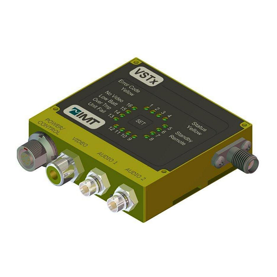
Page 30: Figure 4-3: Vst X - Button & Led Faceplate
User Manual – Button & LED faceplate Figure 4-3: VST – Rotary/Key faceplate Figure 4-4: VST Revision 2.3... -
Page 31: Ribbon Housing
User Manual 4.2.2 Ribbon Housing Screw Holes for Mounting Ribbon Cable Top Surface Antenna Port Ribbon Cable Connector; Arrow points to Pin 1. (26 pins total) Figure 4-5: VSTx - Ribbon Housing Revision 2.3... -
Page 32: Physical Installation
The STx requires installation using proper thermal dissipation methods. During operation, energy is dissipated to the outside environment, especially on the lower surface of the unit. The bottom surface of the VSTx must be kept at a temperature within the operating temperature range specified in Chapter 3. -
Page 33: Connect External Signals (Connector Housing)
IMT has pre-made cables available that support Power and/or RS232 Control. The power portion of the IMT cable has two bare tin leads for connection to an appropriate power source. The control portion of the IMT cable is terminated on a 9-pin D connector. -
Page 34: Figure 4-7: Vstx (Connector Housing) Power/Control Detail
User Manual Table 4-2: VSTx (Connector Housing) Power/Control Pinout Function Notes +12VDC RS232 RX USB DM USB DP RS232 TX USB POWER Not Active GROUND Figure 4-7: VSTx (Connector Housing) Power/Control Detail Revision 2.3... -
Page 35: Figure 4-8: Vstx (Connector Housing) Audio Detail
(Do not attempt to split the cable or use multiple connectors on the end of the ribbon). To terminate the VST ribbon cable, you may use an interface board which is available from IMT, or the following connector: Hirose Electronics Model Number FH33-26s-0.6sh(10) -
Page 36: Table 4-4: Ribbon Cable Connector Cable Pin Assignments
User Manual Table 4-4: Ribbon Cable Connector Cable Pin Assignments Pin on IMT provided Pin # Signal Name Direction Description Interface Board (Z036/Z042/etc) PA AGC PA AGC input for external PA (0 to 3.3VDC) n/aGPI 1 General Purpose Inputs n/aGPI 2... - Page 37 User Manual Chapter Five Operation Revision 2.3...
-
Page 38: Power Up The Vstx
User Manual 5 Operation While this chapter contains basic information about the operation of the VSTx transmitter, the programming of the unit (including preset configuration) via the Nano Controller GUI is not covered. Please refer to the “Nano Controller” manual (IMT Publication: M27-0001-00A) for detailed information on how to program and configure the unit. -
Page 39: User Interfaces
User Manual 5.3 User Interfaces The VSTx will have either a Connector or Ribbon style housing. The Connector style unit will have either a Button & LED faceplate, or a Rotary/Key, or a Blank faceplate. The user interfaces for the various types are described below. -
Page 40: Rotary/Key Interface
User Manual 5.3.2 Rotary/Key Interface This interface allows the user to select presets without requiring a remote control. Changes made remotely will NOT be reflected on the front panel. The interface consists of a 16 position rotary switch. The switch is used to advance through the unit presets, from 1-16. The unit will begin to implement the selected preset after the switch has been idle for 5 seconds. -
Page 41: Ribbon Version
The interface consists of a 26 pin ribbon cable. See Section 4 “Installation” for pin assignments. Ribbon Cable Connector; Ribbon Cable Arrow points to Pin 1. (26 pins total) Figure 5-3: VSTx - Ribbon Version interface Revision 2.3... -
Page 42: Pa Agc Signal
User Manual 5.3.3.1 PA AGC Signal Controls the VSTx RF output level when an external PA is used. The input range is 0 to 3.3VDC. 5.3.3.2 RS232 RX UD This is a RS232 input used to transport RS232 data through the RF link. This signal receives data at a user defined baud rate and encapsulates this data into the MPEG Transport stream. -
Page 43: Using The Vstx To Transmit Audio And Video Signals
The User Data Interface can be used to packetize user data along with the main audio and video information. The User Data can be received and output by compatible IMT receivers. The user data interface must be programmed using the serial interface. -
Page 44: Using Alternate/Custom Controllers
In addition to IMT’s Nano Controller, alternate control interfaces may be developed, or available from third parties. Additionally, commands and responses may be entered and viewed manually using a command terminal. -
Page 45: Troubleshooting
User Manual 5.7 Troubleshooting Table 5-1: Table of Troubleshooting Tips Problem Possible Explanations Actions to Take No Power Check power source Camera Malfunction Try a different camera No video Verify that all modulation type and encryption/decryption Possible Receiver system issue parameters match at transmitter and receiver. - Page 46 User Manual Revision 2.3...
- Page 47 IMT personnel. IMT has made every effort to ensure the accuracy of this material at the time of printing. However, as the specifications, equipment, and this manual are subject to change without notice, IMT assumes no responsibility or liability whatsoever for any errors or inaccuracies that may appear in this manual, or for any decisions based on its use.
- Page 48 Technical Support Information Technical Support personnel are available to extend technical assistance to customers while installing, operating, or troubleshooting IMT equipment. Please have your model number and serial number available. Telephone During IMT business hours, 8:30am - 5:30pm EST (-5 Hours, GMT), call: US ............
- Page 49 User Manual Revision 2.3...
- Page 50 User Manual IMT, LLC. 200 International Drive Mt. Olive, NJ, 07828, USA. T +1 908 852 3700 F +1 908 813 0399 www.imt-solutions.com Revision 2.3...
Need help?
Do you have a question about the VSTx and is the answer not in the manual?
Questions and answers