
Subscribe to Our Youtube Channel
Summary of Contents for Littelfuse MPS
- Page 1 MPS MANUAL MOTOR PROTECTION SYSTEM Revision 6-F-022117 Copyright © 2017 by Littelfuse Startco All rights reserved. Document Number: PM-1130-EN...
- Page 2 Factory default password is 1111 New Password See Section 4.3.6. Motor Identification...
-
Page 3: Table Of Contents
4.2.6 Motor Data ..........4-2 1.2.5 Inputs and Outputs ........1-1 4.2.7 Output Relay Assignment ......4-2 1.2.6 MPS-OPI Operator Interface ..... 1-2 4.2.8 Digital Inputs 1 to 7 ........4-3 1.2.7 MPS-RTD Module ........1-2 4.2.9 Tachometer Input (HSI) ......4-4 1.2.8 MPS-DIF Differential Module .... -
Page 4: Ection
5.21 Underfrequency ..........5-7 Appendix C MPS Modbus Protocol ......C-1 5.22 Overfrequency ............ 5-8 Appendix D MPS A-B DF1 Protocol ......D-1 5.23 Starts per Hour/Time Between Starts ....5-8 Appendix E Communications Database Table ..E-1 5.24 Failure to Accelerate and Underspeed ....5-8 Appendix F Register Formats ........ - Page 5 MPS-CTU with OPI Outline and 6.16 Reactor or Resistor-Starter Connection ....6-10 Mounting Details ............ 2-5 6.17 Slip-Ring-Starter Connection ........ 6-10 2.3.1 MPS-CTU Ring Terminal with OPI Outline and 6.18 Part-Winding and Double-Delta-Starter Mounting Details ............ 2-6 Connections ............6-11 SE-IP65CVR-M Weatherproof Cover Outline ..
-
Page 6: Disclaimer
MPS Motor Protection System Rev. 6-F-022117 ISCLAIMER Specifications are subject to change without notice. Littelfuse Startco is not liable for contingent or consequential damages, or for expenses sustained as a result of incorrect application, incorrect adjustment, or a malfunction. Table of Contents... -
Page 7: Introduction
• Negative-sequence current metering, and data-logging functions. The Control Unit Earth-leakage current • (MPS-CTU) is the core module. It can operate as a stand- Differential currents • alone unit or with the Operator Interface (MPS-OPI), Line-to-line voltages •... -
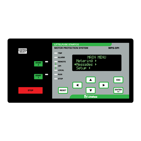
Page 8: Mps-Opi Operator Interface
TCP, and Ethernet/IP. ® SE-Flash ....... Firmware Upgrade Software 1.3 O RDERING NFORMATION See Fig. 1.2 for MPS-CTU, MPS-OPI, MPS-RTD, and Available at www.littelfuse.com/relayscontrols. MPS-DIF model numbers. Earth-Fault Current Sensors: EFCT-1 ......Earth-Fault CT, 5-A-primary rating, 82 mm (3.2”) window EFCT-1FC ..... -
Page 9: Motor Protection System Block Diagram
Page 1-3 MPS Motor Protection System Rev. 6-F-022117 FIGURE 1.1 Motor Protection System Block Diagram. Introduction... -
Page 10: Mps Ordering Information
Page 1-4 MPS Motor Protection System Rev. 6-F-022117 FIGURE 1.2 MPS Ordering Information. Introduction... -
Page 11: Installation
The MPS-RTD can be surface or DIN-rail mounted. 2.5 MPS-DIF D IFFERENTIAL ODULE Outline and mounting details for the MPS-DIF are shown in Fig 2.7. The MPS-DIF can be surface or DIN- rail mounted. 2.6 E CT’ ARTH- AULT Outline and mounting details for the EFCT-1, EFCT-2, EFCT-26, and SE-CS30 series are shown in Figs. -
Page 12: Mps-Ctu Outline And Mounting Details
Page 2-2 MPS Motor Protection System Rev. 6-F-022117 FIGURE 2.1 MPS-CTU Outline and Mounting Details. Installation... -
Page 13: Mps-Ctu-Xx-X1 Ring Terminal Outline And Mounting Details
Page 2-3 MPS Motor Protection System Rev. 6-F-022117 FIGURE 2.1.1 MPS-CTU-XX-X1 Ring Terminal Outline and Mounting Details. Installation... -
Page 14: Mps-Opi Outline And Mounting Details
Page 2-4 MPS Motor Protection System Rev. 6-F-022117 FIGURE 2.2 MPS-OPI Outline and Mounting Details. Installation... -
Page 15: Mps-Ctu With Opi Outline And Mounting Details
Page 2-5 MPS Motor Protection System Rev. 6-F-022117 FIGURE 2.3 MPS-CTU with OPI Outline and Mounting Details. Installation... -
Page 16: Mps-Ctu Ring Terminal With Opi Outline And Mounting Details
Page 2-6 MPS Motor Protection System Rev. 6-F-022117 FIGURE 2.3.1 MPS-CTU Ring Terminal with OPI Outline and Mounting Details. Installation... -
Page 17: Se-Ip65Cvr-M Weatherproof Cover Outline
Page 2-7 MPS Motor Protection System Rev. 6-F-022117 FIGURE 2.4 SE-IP65CVR-M Weatherproof Cover Outline. Installation... -
Page 18: Se-Ip65Cvr-M Weatherproof Cover Installation
Page 2-8 MPS Motor Protection System Rev. 6-F-022117 FIGURE 2.5 SE-IP65CVR-M Weatherproof Cover Installation. Installation... -
Page 19: Mps-Rtd Outline And Mounting Details
Page 2-9 MPS Motor Protection System Rev. 6-F-022117 FIGURE 2.6 MPS-RTD Outline and Mounting Details. Installation... -
Page 20: Mps-Dif Outline And Mounting Details
Page 2-10 MPS Motor Protection System Rev. 6-F-022117 FIGURE 2.7 MPS-DIF Outline and Mounting Details. Installation... -
Page 21: Efct-1 Outline And Mounting Details
Page 2-11 MPS Motor Protection System Rev. 6-F-022117 FIGURE 2.8 EFCT-1 Outline and Mounting Details. Installation... -
Page 22: Efct-2 Outline And Mounting Details
Page 2-12 MPS Motor Protection System Rev. 6-F-022117 FIGURE 2.9 EFCT-2 Outline and Mounting Details. Installation... -
Page 23: Efct-26 And Se-Cs30-26 Outline And Mounting Details
Page 2-13 MPS Motor Protection System Rev. 6-F-022117 FIGURE 2.10 EFCT-26 and SE-CS30-26 Outline and Mounting Details. Installation... -
Page 24: Se-Cs30-70 Outline And Mounting Details
Page 2-14 MPS Motor Protection System Rev. 6-F-022117 FIGURE 2.11 SE-CS30-70 Outline and Mounting Details. Installation... -
Page 25: Se-Cs30-4, -5, And -8 Outline And Mounting Details
Page 2-15 MPS Motor Protection System Rev. 6-F-022117 FIGURE 2.12 SE-CS30-4, -5, and -8 Outline and Mounting Details. Installation... - Page 26 Page 2-16 MPS Motor Protection System Rev. 6-F-022117 This page intentionally left blank. Installation...
-
Page 27: System Wiring
CT-primary rating as communications addressing supports up to three modules defined by the following formula. of each type; however, the power supply in the MPS-CTU will not support more than three I/O modules. external 24-Vdc power supply is required if more than three modules are used. -
Page 28: Typical Mps Connection Diagram
Page 3-2 MPS Motor Protection System Rev. 6-F-022117 FIGURE 3.2 Typical MPS Connection Diagram. System Wiring... -
Page 29: Direct Connection
350 Vac. Since the The 1-PT connection is shown in Fig. 3.4. Connect the MPS-CTU measures line-to-line voltage, there is no PT between phase A and phase B. The PT-secondary advantage in using a 3-PT connection over a 2-PT voltage must be less than 350 Vac. -
Page 30: Dc Operation
COM and connect field inputs between “+” and adjustment, the IRIG Offset set points can be used to the digital-input terminals. adjust the hour and minute values so that the MPS will read local time. 3.2.1.4.2 AC O PERATION Inputs operate over a 12- to 120-Vac range. -
Page 31: Mps-Rtd Connections And Address Selection
It is preferred to use three core-balance CT’s as described in Section 3.2.4.1. This six CT connection TABLE 3.2 MPS-RTD A DDRESS ELECTION allows the CT’s and MPS-DIF to be placed near the motor to minimize power-cable and CT-lead length. DDRESS WITCH WITCH... -
Page 32: Two Examples Of I/O Module Connections
Page 3-6 MPS Motor Protection System Rev. 6-F-022117 FIGURE 3.9 Two Examples of I/O Module Connections. System Wiring... -
Page 33: Mps-Rtd Connection Diagram
Page 3-7 MPS Motor Protection System Rev. 6-F-022117 FIGURE 3.10 MPS-RTD Connection Diagram. System Wiring... -
Page 34: Core Balance Connection
Page 3-8 MPS Motor Protection System Rev. 6-F-022117 FIGURE 3.11 Core Balance Connection. FIGURE 3.12 MPS Summation Connection. System Wiring... -
Page 35: Dif Summation Connection
Page 3-9 MPS Motor Protection System Rev. 6-F-022117 FIGURE 3.13 DIF Summation Connection. System Wiring... - Page 36 Page 3-10 MPS Motor Protection System Rev. 6-F-022117 This page intentionally left blank. System Wiring...
-
Page 37: Operation And Setup
4.1 G ENERAL keys on the MPS-OPI. See the menu map in Appendix A. The MPS-CTU can operate independently. It can also operate in conjunction with network communications, the 4.2 MPS-CTU MPS-OPI, MPS-RTD and the MPS-DIF. -
Page 38: Earth-Fault-Ct Input
Alarm1&3, Alarm2&3, or Alarm1,2,&3. Fail- The Frequency setting determines the sampling rate safe or non-fail-safe mode selection is active. used by the MPS for current and voltage measurements. Local Relay energized when Local starter control is If Sync to ASD is selected as the analog-input type, the selected. -
Page 39: Digital Inputs 1 To 7
Except for overload trips, which can be selected to 2-Wire Start1 1 = Start1 (Maintained) 0 = Stop auto-reset, trips must be reset with an MPS-OPI, a digital 2-Wire Start2 1 = Start2 (Maintained) input, or a network command. A trip cannot be reset 0 = Stop when the trip condition is present. -
Page 40: Tachometer Input (Hsi)
UTPUT Momentary voltage on any input will initiate a start. OPI Menu: Setup | Analog Output | Output Parameter (MPS must be in LOCAL for Local Start1 and Local A 25-mA programmable current output is provided on Start2 operation.) the CTU. -
Page 41: Analog Input
OPI Menu: Setup | 4-20 Analog In ⏐ Metering Only key press. When Metering Only is selected, an analog input does Maintenance Used to: not affect MPS operation, but its value can be observed in Clear event records, trip •... -
Page 42: Starter Control
OPI are the only start source from the start sources enabled in the Remote Group menu. the MPS will respond to. If the OPI has been enabled as a Start source selections are Digital Inputs, OPI, and start source for remote control, the OPI LED will also be Network. -
Page 43: Metering
Display selections for the Summary menu are: is used. All trips are simultaneously reset by digital- • IDR Current-based metering (I), digital input reset, with the MPS-CTU RESET key or with a inputs (D), and relay outputs (R): communications-network command. Alarms are non-... -
Page 44: Metering Display
The number of starts per hour has been exceeded. A start is prevented if a starts-per hour trip or alarm is enabled. Indicates that the MPS is in ETR mode. Does not prevent a start. t° Disabled by ETR Backspin Timer On When a stop is issued and the backspin timer is enabled, a start is prevented until the backspin timer times out. -
Page 45: Data Logging
OPI Menu: Setup | System Config | Maintenance to update the set point, or press ESC to exit the display The MPS records the following statistical data: without changing the set point. A set point is set to the • Running hours. -
Page 46: 4.4 Mps-Rtd
Messages | Re-Start Trace. This allows the enabled. If RTD protection is disabled, metering MPS to be reset and the trip data to be analyzed at a later information is still provided. Up to three modules can be time. -
Page 47: Protective Functions
5.1 G ENERAL menu. One of three states are indicated: Motor:Start, The MPS measures true RMS, peak, and fundamental- Motor:Run, or Motor:Off. The motor status line also frequency values of current and voltage. Fundamental- indicates one of two states for the Reduced Overcurrent frequency values (magnitude and phase angle) are obtained (ROC) feature: ROC:OFF or ROC:ON. - Page 48 Auto mode is selected. A warning label may be required. The MPS provides indication of thermal trend and used thermal capacity. Thermal trend is the value that used In the Multiple Motor Seq. mode, Used I...
-
Page 49: Class-20 Overload Curve
Page 5-3 MPS Motor Protection System Rev. 6-F-022117 t Start Inhibit ...... Enable/Disable Measurement Method ... DFT or RMS Protection ......Enable/Disable Trip1, 2, 3 Enable/Disable Alarm1, 2, 3 FIGURE 5.1 Class-20 Overload Curve. Protective Functions... -
Page 50: Locked-Rotor Times
Trip Delay (TD) ....0.00 to 10.00 s state must be less than 50%. (See Tables 5.1 and 5.2) If the thermal model in the MPS has the correct value Protection ......Enable/Disable Trip1, 2, 3 of T and if Used I t increases by 50% during a start, the Measurement Method ... -
Page 51: Overcurrent
Page 5-5 MPS Motor Protection System Rev. 6-F-022117 The asymmetrical-current multipliers for RMS and Trip Level ......1.00 to 15.00 x CT-Primary DFT measuring methods are shown in Fig. 5.2. X/R is Rating (I the ratio of system reactance to system resistance. -
Page 52: Phase Loss-Current
Page 5-6 MPS Motor Protection System Rev. 6-F-022117 5.12 O Trip Level ......0.05 to 1.00 VERVOLTAGE Trip Delay ......1.00 to 100.00 s OPI Menu: Setup | Protection | Overvoltage Alarm Level ......0.05 to 1.00 A trip or alarm occurs if the maximum line-to-line Alarm Delay ...... -
Page 53: Undervoltage
Page 5-7 MPS Motor Protection System Rev. 6-F-022117 5.16 U 5.19 P —Q NDERVOLTAGE OWER ACTOR UADRANT OPI Menu: Setup | Protection | Undervoltage OPI Menu: Setup | Protection | PF Quandrant4 A trip or alarm occurs if the minimum line-to-line... -
Page 54: Starts Per Hour/Time Between Starts
# Starts Per Hour setting or if the time since the previous Underspeed protection feature is enabled. If the Speed 3 start is less than the Time Between setting. threshold is not reached within Time 3, the MPS will trip When a Starts/Hour Trip or Starts/Hour Alarm is on failure-to-accelerate. -
Page 55: Differential Current Protection
OPI Menu: Setup | Hardware | RTD Module 392°F) Up to three RTD modules can be connected to the Display Range ...... -40.00 to 200.00°C (-40°F to MPS-CTU. Select the number of modules in the Setup | 392°F) Hardware | RTD Modules menu. Each module can Error Codes ...... -
Page 56: Hot-Motor Compensation
HMC Minimum Bias is the stator OPI Menu: Setup | 4-20 Analog In | Sync to ASD temperature where compensation begins at 0% I t. HMC When Sync to ASD is selected, the MPS uses the Maximum Bias stator temperature... -
Page 57: Starter Functions
REMOTE, OPI, and LOCAL LED’s Each Local Select source must de-select local control on the OPI. for the MPS to return to the previous control setting. The digital inputs allow concurrent operation of three t Start Inhibit, Starts per Hour alarms and Interlocks start-control methods;... - Page 58 STOP or when supply voltage is cycled on Contactor status corresponding to Starter RLYA, Starter the MPS. While the backspin timer is on, the Backspin RLYB, Starter RLYC, and Starter RLYD outputs are...
-
Page 59: Typical 3-Wire Control
Page 6-3 MPS Motor Protection System Rev. 6-F-022117 TABLE 6.2 S TARTER UMMARY TART- CTIVE IMERS ONNECTION ETPOINTS ELAYS ONTACTOR TATUS TARTER FLA 2 RLYA RLYB RLYC RLYD IMER UMBER Full-Voltage Non-Reversing Adjustable-Speed Drive Soft-Start Full-Voltage Reversing Two-Speed Two-Winding Reactor or Resistor Closed-... -
Page 60: Starter Timing Sequences
6.2 S TARTER IMING EQUENCES The MPS uses one of six timing sequences to implement the various starter types. These time-based starter sequences are shown in Figs. 6.3 to 6.8. FIGURE 6.3 Starter Sequence 1. FIGURE 6.4 Starter Sequence 2. -
Page 61: Starter Sequence 3
Page 6-5 MPS Motor Protection System Rev. 6-F-022117 FIGURE 6.5 Starter Sequence 3. FIGURE 6.6 Starter Sequence 4. Starter Functions... -
Page 62: Starter Sequence 5
Page 6-6 MPS Motor Protection System Rev. 6-F-022117 FIGURE 6.7 Starter Sequence 5. FIGURE 6.8 Starter Sequence 6. Starter Functions... -
Page 63: Full-Voltage Non-Reversing Starter
Starter RLYA is used as the output to control the ASD. The MPS-CTU has a 4-20 mA input that should be used to synchronize its sampling rate to the ASD output frequency so that all protection and metering values are FIGURE 6.11 Soft-Start-Starter Connection. -
Page 64: Full-Voltage Reversing Starter
Page 6-8 MPS Motor Protection System Rev. 6-F-022117 6.6 F 6.7 T OLTAGE EVERSING TARTER PEED TARTER Sequence: Fig. 6.4 Sequence: Fig. 6.4 Connection: Fig. 6.13, 6.14, and 6.15 Connection: Fig. 6.12 Current Transfer: Not available Current Transfer: Not available... -
Page 65: Two-Speed Constant- And Variable-Torque-Starter Connections
Page 6-9 MPS Motor Protection System Rev. 6-F-022117 FIGURE 6.14 Two-Speed Constant- and Variable-Torque-Starter Connections. FIGURE 6.15 Two-Speed Constant-Horsepower-Starter Connection. Starter Functions... -
Page 66: Reactor Or Resistor Closed-Transition Starter
Page 6-10 MPS Motor Protection System Rev. 6-F-022117 6.8 R 6.9 S EACTOR OR ESISTOR LOSED RANSITION TARTER Sequence: Fig. 6.5 TARTER Sequence: Fig. 6.5 Connection: Fig. 6.17 Connection: Fig. 6.16 Current Transfer: Available Current Transfer: Available The slip-ring starter is a single-stage wound-rotor... -
Page 67: Part-Winding And Double-Delta Starters
Page 6-11 MPS Motor Protection System Rev. 6-F-022117 6.10 P INDING AND OUBLE ELTA TARTERS START1 or START2 initiates the starting sequence by Sequence: Fig. 6.5 activating Starter RLYA. Starter RLYB activates after the Connection: Fig. 6.18 Stage1 Delay. Current Transfer: Available Both starters require two FLA settings. -
Page 68: Soft-Start-With-Bypass Starter
START1 or START2 initiates the sequence. Starter the MPS. There are two solutions: RLYC activates to close the neutral contactor (K3). 1) This option coordinates the MPS Starter RLYB Starter RLYB activates the wye contactor (K2) after the signal with the soft-start and ensures the status Stage1 Delay. -
Page 69: Autotransformer Closed-Transition Starter
Page 6-13 MPS Motor Protection System Rev. 6-F-022117 6.16 W ELTA LOSED RANSITION TARTER Sequence: Fig. 6.8 Connection: Fig. 6.23 Current Transfer: Available START1 or START2 initiates the start sequence. Starter RLYC activates to close the neutral contactor (K3). Starter RLYB activates to close the wye contactor (K2) after the Stage1 Delay. -
Page 70: Wye-Delta Open-Transition-Starter Connection
Page 6-14 MPS Motor Protection System Rev. 6-F-022117 FIGURE 6.21 Wye-Delta Open-Transition-Starter Connection. FIGURE 6.22 Autotransformer Closed-Transition-Starter Connection. Starter Functions... -
Page 71: Wye-Delta Closed-Transition-Starter Connection
Page 6-15 MPS Motor Protection System Rev. 6-F-022117 FIGURE 6.23 Wye-Delta Closed-Transition-Starter Connection. Starter Functions... - Page 72 Page 6-16 MPS Motor Protection System Rev. 6-F-022117 This page intentionally left blank. Starter Functions...
-
Page 73: Theory Of Operation
The OPI is a terminal device used to communicate with 7.1 S IGNAL ROCESSING LGORITHMS the MPS-CTU. All set points, operating parameters, and The sampling frequency of the MPS is variable. It can menus are stored in the MPS-CTU. 50-Hz, 60-Hz, variable-frequency contains... - Page 74 Page 7-2 MPS Motor Protection System Rev. 6-F-022117 When upgrading an MPS that did not previously support the diagnostic error code, the initial value of the diagnostic code is not valid and should be cleared. A diagnostic error generates a Trip1 and increments the trip counter;...
-
Page 75: Communications
• Basic Motor Starter (3) SE-Comm-RIS extends the event-record storage capability • Extended Contactor of the MPS by allowing the user to transfer data to PC • Extended Motor Starter memory at a programmable interval. Protection curve An Electronic Data Sheet (EDS) file is provided for use plotting capability is included. - Page 76 Page 8-2 MPS Motor Protection System Rev. 6-F-022117 This page intentionally left blank. Technical Specifications...
-
Page 77: Technical Specifications
Page 9-1 MPS Motor Protection System Rev. 6-F-022117 9. T (4, 5) ECHNICAL PECIFICATIONS Phase-Voltage Inputs: Nominal Input ..... 30 to 600 Vac line-to-line 9.1 C (MPS-CTU) ONTROL Input Resistance ....3.4 MW Supply ........25 VA, 120 to 240 Vac Range ........ - Page 78 Page 9-2 MPS Motor Protection System Rev. 6-F-022117 Starter-Control Stop Time: Standard Network Communications: Digital Input ......30 to 80 ms Configuration ...... RS-485, 2-wire multi-drop OPI ........70 to 200 ms Baud Rate ......1.2, 2.4, 4.8, 9.6, 19.2 Network .......
-
Page 79: Operator Interface (Mps-Opi)
Page 9-3 MPS Motor Protection System Rev. 6-F-022117 9.2 O (MPS-OPI) PERATOR NTERFACE Australia, Regulatory Compliance Mark (RCM) Supply ........24 Vdc Nominal (20 to 30 9.3 RTD M (MPS-RTD) ODULE Vdc), 80 mA Supply ........16 to 32 Vdc, 90 mA Display Type ...... -
Page 80: Differential Module (Mps-Dif)
Timing Accuracy ....5%, minimum trip time, MPS direct-voltage connection is used. Range is set point +20 ms (11) UL has evaluated the MPS for use with 60 ° / 75 ° C to set point +150 ms, conductors. median 81 ms... -
Page 81: Warranty
MPS Motor Protection System Rev. 6-F-022117 10. W ARRANTY The MPS Motor Protection System is warranted to be free from defects in material and workmanship for a period ten years from the date of purchase. Littelfuse Startco will (at Littelfuse Startco’s option) - Page 82 Page 9-6 MPS Motor Protection System Rev. 6-F-022117 This page intentionally left blank. Technical Specifications...
-
Page 83: Appendix A Mps-Opi Menu Map
Page A-1 MPS Motor Protection System Rev. 6-F-022117 PPENDIX MPS-OPI M Appendix A, MPS-OPI Menu Map... - Page 84 Page A-2 MPS Motor Protection System Rev. 6-F-022117 Appendix A, MPS-OPI Menu Map...
- Page 85 Page A-3 MPS Motor Protection System Rev. 6-F-022117 Appendix A, MPS-OPI Menu Map...
- Page 86 Page A-4 MPS Motor Protection System Rev. 6-F-022117 Appendix A, MPS-OPI Menu Map...
- Page 87 Page A-5 MPS Motor Protection System Rev. 6-F-022117 Appendix A, MPS-OPI Menu Map...
- Page 88 Page A-6 MPS Motor Protection System Rev. 6-F-022117 Appendix A, MPS-OPI Menu Map...
-
Page 89: Appendix B Mps Set-Up Record
Page B-1 MPS Motor Protection System Rev. 6-F-022117 PPENDIX MPS S ECORD Motor: _____________________________ MPS S/N: __________________________ Date: _____________________ Firmware Revision:___________________________ PART I: SYSTEM AND MOTOR PARAMETERS ARAMETER ETTINGS EFAULT ROGRAM ELECTION System Ratings PH-CT Primary (I 100.00 5,000 EF-CT Primary (I 5.00... - Page 90 Disable Remote Select Enable q Enable q Disable OPI Select Enable q Enable q Disable Local Select Enable RTD Modules Total Modules q Disable q Trip1 RTD-Module-Error Trip Action Disable q Trip2 q Trip3 Appendix B, MPS Set-Up Record...
- Page 91 0.10 0.50 is Phase-CT-Primary Rating) Firmware Revision See Protection | System Config | Maintenance | Firmware Version q Enable q Disable Trace Auto-Start Disable Error rate is 1 byte/120 kB. For high reliability, use SCI9600. Appendix B, MPS Set-Up Record...
- Page 92 Trip2 q Trip3 Trip Level 10.00 is Phase-CT-Primary Rating) Trip Delay 0.05 Auxiliary Overcurrent q Disable q Trip1 Trip Action Disable q Trip2 q Trip3 Trip Level 10.00 is Phase-CT-Primary Rating) Trip Delay 0.05 Appendix B, MPS Set-Up Record...
- Page 93 Trip3 Phase Loss Delay 5.00 Phase Reverse (I) q Disable q Trip1 Trip Action Disable q Trip2 q Trip3 q Disable q Alarm1 Alarm Action Alarm1 q Alarm2 q Alarm3 Trip and Alarm Delay 2.00 Appendix B, MPS Set-Up Record...
- Page 94 PF Quadrant 4 q Disable q Trip1 Trip Action Disable q Trip2 q Trip3 Trip Level 0.80 Trip Delay 5.00 q Disable q Alarm1 Alarm Action Disable q Alarm2 q Alarm3 Alarm Level 0.90 Alarm Delay 5.00 Appendix B, MPS Set-Up Record...
- Page 95 Alarm Level Alarm Delay Overfrequency q Disable q Trip1 Trip Action Disable q Trip2 q Trip3 Trip Level Trip Delay q Disable q Alarm1 Alarm Action Disable q Alarm2 q Alarm3 Alarm Level Alarm Delay Appendix B, MPS Set-Up Record...
- Page 96 Alarm Delay 5.00 Starts/Hour q Disable q Trip1 Trip Action Disable q Trip2 q Trip3 q Disable q Alarm1 Alarm Action q Alarm2 q Alarm3 Number of Starts/Hour Time Between Starts 0.00 Appendix B, MPS Set-Up Record...
- Page 97 Cu10 Ω Type Disable q Ni100 Ω q Stator q Load q Bearing q Ambient Function Stator q Stator Voting q Load Voting q Bearing Voting q Ambient Voting Trip 130.00 °C Alarm 110.00 °C Appendix B, MPS Set-Up Record...
- Page 98 Cu10 Ω Type Disable q Ni100 Ω q Stator q Load q Bearing q Ambient Function Stator q Stator Voting q Load Voting q Ambient Voting q Bearing Voting Trip 130.00 °C Alarm 110.00 °C Appendix B, MPS Set-Up Record...
- Page 99 Cu10 Ω Type Disable q Ni100 Ω q Stator q Load q Bearing q Ambient Function Stator q Stator Voting q Load Voting q Ambient Voting q Bearing Voting Trip 130.00 °C Alarm 110.00 °C Appendix B, MPS Set-Up Record...
- Page 100 Cu10 Ω Type Disable q Ni100 Ω q Stator q Load q Bearing q Ambient Function Stator q Stator Voting q Load Voting q Ambient Voting q Bearing Voting Trip 130.00 °C Alarm 110.00 °C Appendix B, MPS Set-Up Record...
- Page 101 Cu10 Ω Type Disable q Ni100 Ω q Stator q Load q Bearing q Ambient Function Stator q Stator Voting q Load Voting q Bearing Voting q Ambient Voting Trip 130.00 °C Alarm 110.00 °C Appendix B, MPS Set-Up Record...
- Page 102 Disable q Cu10 Ω q Ni100 Ω q Stator q Load q Bearing q Ambient Function Stator q Stator Voting q Load Voting q Bearing Voting q Ambient Voting Trip 130.00 °C Alarm 110.00 °C Appendix B, MPS Set-Up Record...
-
Page 103: Appendix C Mps Modbus Protocol
3.5 characters exists within the message, the Byte 1 Slave Address message is discarded. Byte 2 Function Code Response messages from the MPS are delayed by at least Byte 3 MSB Register Address 3.5 character delays. Byte 4 LSB Register Address... - Page 104 MPS Motor Protection System Rev. 6-F-022117 The addressed slave responds with its address and The MPS will reply with the slave address, function code, Function Code 3, followed by the information field. The register address, and the quantity followed by the CRC code information field contains an 8-bit byte count and the 16-bit for a total of 8 bytes.
-
Page 105: Appendix E Communications Database Table
C.6 N ETWORK IMEOUT command code is not supported. The MPS can be configured to trip or alarm on a network Illegal Function Code (4)—The function code (Byte 2) • is not supported. timeout using the Setup | Hardware | Network Comms menu. - Page 106 Page C-4 MPS Motor Protection System Rev. 6-F-022117 This page intentionally left blank. Appendix C, MPS Modbus Protocol...
- Page 107 Set the Channel-0 baud rate and CRC to (DF1) as described in Allen-Bradley Bulletin 1770-6.5.16 match the MPS settings. The parity bit is not supported October 1996. This publication is available from the A-B on the MPS. Where applicable, set Reply Message Wait web site at www.ab.com.
- Page 108 OMMAND CTION 0x0000 STOP 0x0001 START1 If an MPS float has been read into the PLC as two 0x0002 START2 integers and stored in an N-type file, the float can be 0x0003 Reset Trips recovered by using two copy commands. Assume that the...
- Page 109 D.9 N NPROTECTED RITE ETWORK IMEOUT For PLC-2 and PLC-3 processors not supporting Typed The MPS can be configured to trip or alarm on a network Read/Write messages, Unprotected Read/Write timeout using the Setup | Hardware | Network Comms commands can be used. For these messages, the data menu.
- Page 110 Page D-4 MPS Motor Protection System Rev. 6-F-022117 This page intentionally left blank. Appendix D, MPS A-B DF1 Protocol...
- Page 111 Page E-1 MPS Motor Protection System Rev. 6-F-022117 PPENDIX V. 3.04 OMMUNICATIONS ATABASE ABLE ODBUS A-B F EGISTER EGISTER ECIMAL ESCRIPTION CCESS ANGE ECIMAL ECIMAL Model Information 40001 3:000 Model Code (201) Read Only Software Version Read Only Serial Number...
- Page 112 Page E-2 MPS Motor Protection System Rev. 6-F-022117 ODBUS A-B F EGISTER EGISTER ECIMAL ESCRIPTION CCESS ANGE ECIMAL ECIMAL Reduced Overcurrent 40046 3:45 Trip Action 0 - 7 Trip Level 1 - 15 x I T1 (Low) T1 (High) Earth Fault...
- Page 113 Page E-3 MPS Motor Protection System Rev. 6-F-022117 ODBUS A-B F EGISTER EGISTER ECIMAL ESCRIPTION CCESS ANGE ECIMAL ECIMAL Phase Loss (I) 40100 3:99 Trip Action 0 - 7 Trip Delay 1 - 100 s T1(Low) T1(High) Voltage Unbalance 40105...
- Page 114 Page E-4 MPS Motor Protection System Rev. 6-F-022117 ODBUS A-B F EGISTER EGISTER ECIMAL ESCRIPTION CCESS ANGE ECIMAL ECIMAL Speed 2 1 - 100%-FS T1(Low) T1(High) Time 2 1 - 1,000 s T1(Low) T1(High) Speed 3 1 - 100% FS...
- Page 115 Page E-5 MPS Motor Protection System Rev. 6-F-022117 ODBUS A-B F EGISTER EGISTER ECIMAL ESCRIPTION CCESS ANGE ECIMAL ECIMAL Phase-CT Primary 1 - 5,000 A T1(Low) T1(High) EF-CT Primary 1 - 5,000 A T1(Low) T1(High) Input-Voltage Rating 60 V - 600V...
- Page 116 Page E-6 MPS Motor Protection System Rev. 6-F-022117 ODBUS A-B F EGISTER EGISTER ECIMAL ESCRIPTION CCESS ANGE ECIMAL ECIMAL Stage 3 Delay 0.1 - 500 T1(Low) T1(High) Backspin-Timer Enable 0 - 1 Backspin-Time Delay 0.1 - 3,600 s T1(Low) T1(High)
- Page 117 Page E-7 MPS Motor Protection System Rev. 6-F-022117 ODBUS A-B F EGISTER EGISTER ECIMAL ESCRIPTION CCESS ANGE ECIMAL ECIMAL Input 6 Function 0 - 19 Input 6 Bypass Enable 0 - 1 Input 6 Bypass Delay 0.5 - 100 s...
- Page 118 Page E-8 MPS Motor Protection System Rev. 6-F-022117 ODBUS A-B F EGISTER EGISTER ECIMAL ESCRIPTION CCESS ANGE ECIMAL ECIMAL ASD 4-mA Frequency 0 - 70 Hz T1(Low) T1(High) ASD 20-mA Frequency 0 - 70 Hz T1(Low) T1(High) Motor 4-mA Speed...
- Page 119 Page E-9 MPS Motor Protection System Rev. 6-F-022117 ODBUS A-B F EGISTER EGISTER ECIMAL ESCRIPTION CCESS ANGE ECIMAL ECIMAL Module 3 #1 Type 0 - 4 Module 3 #2 Type 0 - 4 Module 3 #3 Type 0 - 4...
- Page 120 Page E-10 MPS Motor Protection System Rev. 6-F-022117 ODBUS A-B F EGISTER EGISTER ECIMAL ESCRIPTION CCESS ANGE ECIMAL ECIMAL Module 1 #3 Alarm Level 40 - 200°C T1(Low) T1(High) Module 1 #4 Trip Level 40 - 200°C T1(Low) T1(High) Module 1 #4 Alarm Level 40 - 200°C...
- Page 121 Page E-11 MPS Motor Protection System Rev. 6-F-022117 ODBUS A-B F EGISTER EGISTER ECIMAL ESCRIPTION CCESS ANGE ECIMAL ECIMAL Module 2 #6 Alarm Level 40 - 200°C T1(Low) T1(High) Module 2 #7 Trip Level 40 - 200°C T1(Low) T1(High) Module 2 #7 Alarm Level 40 - 200°C...
- Page 122 Page E-12 MPS Motor Protection System Rev. 6-F-022117 ODBUS A-B F EGISTER EGISTER ECIMAL ESCRIPTION CCESS ANGE ECIMAL ECIMAL Hot Motor Compensation 40551 4:160 HMC Enable HMC Maximum Bias 40 - 200°C T1(Low) T1(High) HMC Minimum Bias 40 - 200°C...
- Page 123 Page E-13 MPS Motor Protection System Rev. 6-F-022117 ODBUS A-B F EGISTER EGISTER ECIMAL ESCRIPTION CCESS ANGE ECIMAL ECIMAL Analog Output Calibration 40857 5:282 Analog-Output Calibration (Zero) 0 - 1,000 T1(Low) T1(High) Analog-Output Calibration (FS) 0 - 1,000 T1(Low) T1(High)
- Page 124 Page E-14 MPS Motor Protection System Rev. 6-F-022117 ODBUS A-B F EGISTER EGISTER ECIMAL ESCRIPTION CCESS ANGE ECIMAL ECIMAL Unbalance Voltage (pu) Read Only T1(Low) T1(High) Motor Speed From Tach. (RPM) Read Only T1(Low) T1(High) Module 1 #1 Temperature Read Only...
- Page 125 Page E-15 MPS Motor Protection System Rev. 6-F-022117 ODBUS A-B F EGISTER EGISTER ECIMAL ESCRIPTION CCESS ANGE ECIMAL ECIMAL Module 3 #5 Temperature Read Only T1(Low) T1(High) Module 3 #6 Temperature Read Only T1(Low) T1(High) Module 3 #7 Temperature Read Only...
- Page 126 Page E-16 MPS Motor Protection System Rev. 6-F-022117 ODBUS A-B F EGISTER EGISTER ECIMAL ESCRIPTION CCESS ANGE ECIMAL ECIMAL Read Only T1(Low) T1(High) Read Only T1(Low) T1(High) Read Only T1(Low) T1(High) Analog Input Read Only T1(Low) T1(High) Current Unbalance Read Only...
- Page 127 Page E-17 MPS Motor Protection System Rev. 6-F-022117 ODBUS A-B F EGISTER EGISTER ECIMAL ESCRIPTION CCESS ANGE ECIMAL ECIMAL 1033 Module 2 #7 Temperature Read Only T1(Low) 1034 T1(High) 1035 Module 2 #8 Temperature Read Only T1(Low) 1036 T1(High) 1037...
- Page 128 Page E-18 MPS Motor Protection System Rev. 6-F-022117 A-B F ODBUS EGISTER EGISTER ECIMAL ESCRIPTION CCESS ANGE ECIMAL ECIMAL 1084 T1(Low) 1085 Alarm Level 0.1 - 1.0 T1(High) 1086 T1(Low) 1087 Alarm Delay 10.5 - 500 s T1(High) 1088 T1(Low)
- Page 129 Page E-19 MPS Motor Protection System Rev. 6-F-022117 A-B F ODBUS EGISTER EGISTER ECIMAL ESCRIPTION CCESS ANGE ECIMAL ECIMAL 1158 RTD Module 1 #3 Read Only 1159 RTD Module 1 #4 Read Only 1160 RTD Module 1 #5 Read Only...
- Page 130 Page E-20 MPS Motor Protection System Rev. 6-F-022117 A-B F ODBUS EGISTER EGISTER ECIMAL ESCRIPTION CCESS ANGE ECIMAL ECIMAL 1214 T4(Word 3) 1215 T4(Word 4) 1216 kVA Seconds Read Only T4(Word 1) 1217 T4(Word 2) 1218 T4(Word 3) 1219 T4(Word 4)
- Page 131 Page E-21 MPS Motor Protection System Rev. 6-F-022117 A-B F ODBUS EGISTER EGISTER ECIMAL) ESCRIPTION CCESS ANGE ECIMAL) ECIMAL) OTE 4) 1255 Alarm Level 0.5 - 1.0 T1(Low) 1256 T1(High) 1257 Alarm Delay 0.2 - 500 s T1(Low) 1258 T1(High)
- Page 132 Page E-22 MPS Motor Protection System Rev. 6-F-022117 A-B F ODBUS EGISTER EGISTER ECIMAL) ESCRIPTION CCESS ANGE ECIMAL) ECIMAL) OTE 4) 1342 Trace Memory 1343 Trace Memory 1344 Trace Memory 1345 Trace Memory 1346 Trace Memory 1347 Trace Memory 1348...
- Page 133 Page E-23 MPS Motor Protection System Rev. 6-F-022117 A-B F ODBUS EGISTER EGISTER ECIMAL ESCRIPTION CCESS ANGE ECIMAL ECIMAL User Defined Registers 1400 41401 9:190 User Register 0 1401 User Register 1 1402 User Register 2 1403 User Register 3...
- Page 134 = Trace Value x (V ) x 0.00043358 kV primary secondary are calculated from V The following MPS-RTD error codes are supported: -100 = No RTD Sensor -90 = Open Sensor -80 = Shorted Sensor -70 = No Data/Module Communication Error...
-
Page 135: Appendix F Register Formats
Page F-1 MPS Motor Protection System Rev. 6-F-022117 PPENDIX EGISTER ORMATS ESCRIPTION Float IEEE 32-Bit Floating-Point Number Bit 31: Sign Bits 30..23: Exponent Bits 22..0: Mantissa Float (High): Bits 31..16 Float (Low): Bits 15..0 Long 32-Bit Integer (High) Bits 31..16 (Low) Bits 15..0... - Page 136 Page F-2 MPS Motor Protection System Rev. 6-F-022117 ESCRIPTION Short Digital Input Function 0: Input Not Used 1: Start 1 (N.O. Contact) 2: Start 2 (N.O. Contact) 3: Stop (N.C. Contact) 4: Starter RLYA Status 5: Starter RLYB Status 6: Starter RLYC Status 7: Starter RLYD Status 8: Interlock (N.C.)
- Page 137 Page F-3 MPS Motor Protection System Rev. 6-F-022117 ESCRIPTION Short Analog Output Function 0: Phase Current 1: Earth Leakage 2: Thermal Capacity 3: Stator RTD 4: Bearing RTD 5: Load RTD 6: Ambient RTD 7: Voltage 8: Unbalance (I) 9: Power Factor...
- Page 138 Page F-4 MPS Motor Protection System Rev. 6-F-022117 ESCRIPTION Short RTD Function 0: Stator 1: Bearing 2: Load 3: Ambient 4: Stator Voting 5: Bearing Voting 6: Load Voting 7: Ambient Voting Char 20 ASCII characters Register +0: Char[0] and Char[1]. Char [0] at MSByte Register +1: Char[2] and Char[3].
- Page 139 Page F-5 MPS Motor Protection System Rev. 6-F-022117 ESCRIPTION Short Trigger Source 0: Empty Record 1: Trip Record 2: Start Record 3: ETR Record Short Message Code 0: Main Overcurrent Trip 1: Auxiliary Overcurrent Trip 2: Overload Trip 3: Overload Alarm...
- Page 140 Page F-6 MPS Motor Protection System Rev. 6-F-022117 ESCRIPTION 41: RTD Module 1 INP 3 Trip 42: RTD Module 1 INP 3 Alarm 43: RTD Module 1 INP 4 Trip 44: RTD Module 1 INP 4 Alarm 45: RTD Module 1 INP 5 Trip...
- Page 141 Page F-7 MPS Motor Protection System Rev. 6-F-022117 ESCRIPTION 89: RTD Module 3 Comm Trip 90: RTD Module 3 Comm Alarm 91: RTD Sensor-Failure Trip 92: RTD Sensor-Failure Alarm 93: Thermal Lockout 94: All Defaults Loaded 95: Non-Volatile Memory (NV) Enumeration Error...
- Page 142 Page F-8 MPS Motor Protection System Rev. 6-F-022117 ESCRIPTION Bit3: 1 = Motor Current > 125% FLA Bit4: 1 = Temperature Set Point Bypassed Bit5: 1 = Reduced Overcurrent Operational Short Starter Sequencer Status 1: Start1 2: Run1 3: Start2...
- Page 143 Page F-9 MPS Motor Protection System Rev. 6-F-022117 ESCRIPTION Bit2: 1 = Relay 3 Energized Bit3: 1 = Relay 4 Energized Bit4: 1 = Relay 5 Energized Short MPS Command 0: Stop 1: Start 1 2: Start 2 3: Reset Trips...
- Page 144 Page F-10 MPS Motor Protection System Rev. 6-F-022117 ESCRIPTION 5: Alarm1 & Alarm3 6: Alarm1 & Alarm2 & Alarm3 7: Alarm2 & Alarm3 Short DeviceNet Producing Instance 0: None 1: 0x32 Basic Overload 2: 0x33 Extended Overload 3: 0x34 Basic Motor Starter...
-
Page 145: Appendix G Mps Revision History
Threshold setpoint added to Sections 5.8, 5.19, and 5.20. ECTION RCM Certification added. PPENDIX System Config menu updated. PPENDIX Threshold setpoint added. PPENDIX MPS registers 220 and 221 added. 6-D-060815 EVISION ECTION RTD protection updated in Section 4.4. ECTION Section 5.24 updated. Appendix G, MPS Revision History... - Page 146 MPS Motor Protection System Rev. 6-F-022117 PPENDIX RTD temperature menu updated. PPENDIX RTD modules updated. PPENDIX MPS registers 548 and 549 added. 6-C-011515 EVISION ECTION Figs. 2.8, 2.9, 2.10, and 2.11 updated. ECTION OPI menu updated in Section 5.24. 6-B-061914...
- Page 147 RTD temperature trip now occurs when temperature is equal to or greater. 3.15 IRMWARE EVISION HMC Compensation limit is set to 0.9 (90%). Added feature to initiate MPS upgrade mode using OPI. 3.14 IRMWARE EVISION Fixed RTD reading for unused RTDs.
- Page 148 G.4 MPS-DIF REVISION HISTORY MANUAL MANUAL PRODUCT REVISION RELEASE DATE REVISION (REVISION NUMBER ON PRODUCT LABEL) 6-C-011515 January 15, 2015 6-B-061914 June 19, 2014 6-A-101813 October 18, 2013 November 2007 RODUCT EVISION ISTORY RODUCT EVISION Initial Release. Appendix G, MPS Revision History...
Need help?
Do you have a question about the MPS and is the answer not in the manual?
Questions and answers