Table of Contents
Advertisement
2
3
1
4
5
7
1: ActiGait® Heel Switch
2: ActiGait® Belt Loop
3: ActiGait® Body Clip
4: ActiGait® Belt Clip
5: ActiGait® Control Unit
6: ActiGait® Antenna
7: ActiGait® Heel Sock
8: ActiGait® Antenna Fixture
6
8
9: ActiGait® Charger (model FW7711/0.7) incl. plugs
10: ActiGait® Charger Cable
9a
9b
9c
10
9d
9
Advertisement
Table of Contents

Subscribe to Our Youtube Channel
Summary of Contents for Otto Bock ActiGait
- Page 1 1: ActiGait® Heel Switch 9: ActiGait® Charger (model FW7711/0.7) incl. plugs 2: ActiGait® Belt Loop 10: ActiGait® Charger Cable 3: ActiGait® Body Clip 4: ActiGait® Belt Clip 5: ActiGait® Control Unit 6: ActiGait® Antenna 7: ActiGait® Heel Sock 8: ActiGait® Antenna Fixture...
- Page 2 ActiGait® Implantable Drop Foot Stimulator User Manual...
-
Page 3: Table Of Contents
7.1.5 The Control Unit Battery Indicator ..22 14.8 ActiGait® Heel Sock ......59 7.1.6 The Heel Switch Battery Indicator ..23 14.9 19.9 ActiGait® Charger Cable ....59 7.1.7 Training Mode Indicator ...... 25 14.10 ActiGait® Charger ......60 7.1.8 Mute Indicator ........ -
Page 4: Introduction
For clinicians the Clinician Manual (647G805=GB) is available 2. Intended Use 2.1 Medical Purpose The ActiGait® is solely to be used as treatment in patients having a drop foot follow- ing an upper motor neuron lesion. 2.2 Application The ActiGait® system is a partially implantable medical device for treatment of drop foot which activates the muscles of the lower leg during walking. -
Page 5: Indications/Contraindications
Potential candidates for the ActiGait® are stroke patients with drop foot. The pa- tients who may benefit from use of the ActiGait® are characterized by lacking the ability to obtain normal heel contact during gait. It must be possible to correct the heel contact by electrical stimulation of the peroneal nerve. -
Page 6: Warnings And Precautions
ActiGait®. 4.2 Warnings • The ActiGait® is a device for treatment of drop foot, and must be considered and used accordingly. Stimulation of other nerves besides the peroneal nerve with the ActiGait® involves a risk of potentially hazardous side effects. It is not meant as a device that eliminates or cures any condition. - Page 7 • ActiGait® patients should not engage in any activity which leaves them in a dan- gerous situation if the ActiGait® fails. • The ActiGait® should not be exposed to therapeutic levels of ultrasound energy, as the device may inadvertently concentrate the ultrasound field and cause harm.
-
Page 8: General Cautions
• Consult the dealer or an experienced radio/TV technician for help 2 In warm weather you must be extra aware of skin irritation where the ActiGait® is in contact with your skin. In case of skin irritation you should remove the ActiGait®. - Page 9 ActiGait®. • The external parts of the ActiGait® must be turned off on airplanes during a flight, as the radio transmission may interfere with other devices. Because the Heel Switch cannot be turned off it should be taken off and removed from the body during the flight to avoid activation of the switch.
-
Page 10: Potential Risks/Side Effects
ActiGait® may leave the patient in a dangerous situation. • The ActiGait® fulfills all technical and legal requirements for use in the European Community. The ActiGait® has not yet been formally investigated for use outside this area. - Page 11 • Nerve damage in the case of the cuff electrode constricting the nerve • Skin reactions to the material of the external components of the ActiGait® (Heel Switch and Antenna Fixture) in permanent contact with the body • Device extrusion/migration •...
-
Page 12: Service Information
5. Service Information 5.1 Scope of Delivery The term “ActiGait®” is defined as the parts of the system that you have in or on your body. Besides this you will be given various “ActiGait® accessories” that you need for maintaining your ActiGait®. To be able to use the ActiGait® system you will need the... -
Page 13: Description Of The Actigait
Cuff Electrode Heel Switch Figure 1: The Implant and other main parts of the ActiGait® and their locations during use. The purpose of the ActiGait®is to lift your foot during the swing phase of walking. When you walk, the Heel Switch detects your heel strike and heel lift and transmits signals wirelessly to the Control Unit. -
Page 14: The Actigait® Implant
The Implant does not have an internal power source (such as a battery) and is ac- tivated through magnetic induction from an external power source. The Implant is as such passive, and it is necessary to have an ActiGait® Control Unit and ActiGait® Antenna to activate it. -
Page 15: The Actigait
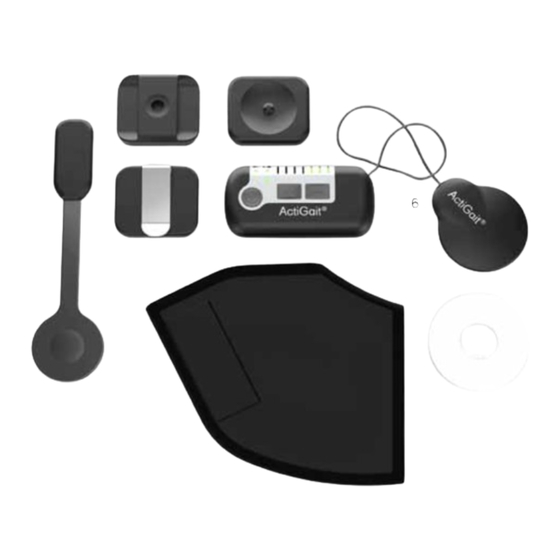
Belt Clip (4), the Control Unit (5), the Antenna (6), the Heel Sock (7) and the Antenna Fixture (8) (see Figure 3). Figure 3: The ActiGait®. 1: Heel Switch, 2: Belt Loop, 3: Body Clip, 4: Belt Clip, 5: Control Unit, 6: An- tenna, 7: Heel Sock, 8: Antenna Fixture... -
Page 16: How Actigait® Works
Travel Kit for the Charger consisting of 4 different plugs (9), the Charger (10) and the Charger Cable (11). Figure 4: ActiGait® accessories. 9: Travel kit for Charger, 10: Charger, 11: Charger Cable 7. How ActiGait® works When you receive your ActiGait®, the package will contain the items shown in Figure 3 and Figure 4. -
Page 17: The Control Unit
7.1 The Control Unit The Control Unit (Figure 5) controls the implanted stimulator via the Antenna, which must be located on the skin on top of the implanted stimulator. The Control Unit receives signals from the Heel Switch (see section 7.5 on page 35) about when to stimulate. -
Page 18: The On/Off Button
• Mute indicator: Section 7.1.8 on page 27, page 36 7.1.1 The On/Off Button The on/off button is used for switching the ActiGait® Control Unit on and off. You must press the on/off button for at least 1.5 seconds to activate it. -
Page 19: The Stimulation Intensity Buttons
Every time the Control Unit is switched on it performs an indicator check. This means that all light indicators will flash once and a short beep is heard. This can be used for diagnostics because it shows if any of the light indicators or the buzzer is defect. -
Page 20: The Mute Button
The row of light indicators on top of the Control Unit shows the current intensity level of the stimulation. There are 7 light indicators so the stimulation intensity can be adjusted in 7 steps. Your clinician will set the range within which you can adjust the stimulation intensity with the Control Unit. - Page 21 The mute button has three settings: All sounds are on. All sounds are on, except for the Heel Switch feed- back. All sounds are off, except for warnings. As default, all sounds are activated and therefore the mute light indicator is green. If you press the mute button once, the light indicator turns yellow and if you press it once more, it turns red.
-
Page 22: The Pairing Button
7.1.4 The Pairing Button To avoid that another user’s Heel Switch can communicate with your Control Unit, your Control Unit must be set up to only recognize your Heel Switch. This is called pairing. The pairing button is a pencil button hidden under the Antenna plug below the mute button. -
Page 23: The Control Unit Battery Indicator
The Control Unit is powered by an internal rechargeable battery. You must charge the Control Unit with the ActiGait® Charger and it is recommended that you make a habit of charging the Control Unit regularly, e.g. every night (see section 7.6 on page 38 about the Charger and how to charge the Control Unit). -
Page 24: The Heel Switch Battery Indicator
The battery level of the Control Unit is normal and you have power for at least one day of walking. The battery level of the Control Unit is medium and you have power for less than one day. Red and the Control Unit beeps once every 30 sec- onds: The battery level is low and you have power for less than 2 hours. - Page 25 The battery indicator for the Heel Switch is shown by the top left light icon on the Control Unit. The Heel Switch battery indicator. The Heel Switch battery indicator can be green, yellow or red reflecting how much power you have left on the Heel Switch. The battery level of the Heel Switch is normal and you have power for at least 3 months.
-
Page 26: Training Mode Indicator
The Training Mode indicator flashes when the Control Unit is in Training Mode. The Training Mode is used to increase your muscle strength and endurance, and to inhibit spasticity. In Training Mode the ActiGait® Implant is cyclically activated without an input from the Heel Switch, e.g. during sitting or lying down. Training Mode will automatically be turned off if the Heel Switch is activated during training so Training Mode cannot be used for walking. - Page 27 Press the on/off button and either of the intensity buttons at the same time for at least 1.5 seconds. The Training Mode light indicator flashes as long as the Control Unit is in Training Mode. Continue training for as long as recommended by your clinician.
-
Page 28: Mute Indicator
7.1.8 Mute Indicator With the mute functionality you can switch the audio signals of the Control Unit on and off according to your preference. There are 3 different settings and the mute indicator shows the current setting. All sounds are on. All sounds are on, except for the Heel Switch feed- back. -
Page 29: The Belt Clip
7.2.1 The Belt Clip The Belt Clip is suitable if you want to attach the Control Unit to e.g. the waist line of a pair of trousers or a skirt or at the lining of your pocket. Attach the Belt Clip to your clothing, e.g. your waistline or a pocket…... -
Page 30: The Body Clip
.put the belt on and slide the Belt Loop to the right position..orient the Control Unit as shown and slide it against the Belt Loop to fix the two together The Control Unit is held in place by magnets inside both the Control Unit and the Belt Loop. -
Page 31: Putting On The Antenna Fixture
Insert the knob of the Body Clip into the opening in the plastic part of the fixture and push the Body Clip downwards until you hear a click. Orient the Control Unit as shown and slide it against the Body Clip to fix the two together. The Control Unit is held in place by magnets inside both the Control Unit and the Body Clip. - Page 32 Adhesive Bearing Liner Applicator Liner Figure 7: The 3 layers of the Antenna Fixture Place the Antenna Fixture on a table with the bearing liner facing upwards. Peel off the first part of the bearing liner. Do not touch the adhesive side as this will decrease its adhesiveness.
- Page 33 Peel off the remaining part of the bearing liner. Press the entire Antenna Fixture firmly onto the skin to warm it up and ensure the adhesiveness of the fixture. Keep the pressure for 30 seconds. Finally, remove the applicator liner on the front of the Antenna Fixture.
-
Page 34: Putting On The Antenna
If you experience any skin irritation where the Antenna Fixture is placed, you should stop using the fixture and your ActiGait® for a while. If the problem contin- ues, contact your clinician. 7.4 Putting On the Antenna When you have attached the Antenna Fixture to your thigh above the Implant, you can click the Antenna into the Fixture. - Page 35 You can turn the Antenna plug both ways so that the Antenna Cable comes out at the top or at the bottom of the Control Unit. Make sure you attach the Antenna plug properly to ensure the connection to the Control Unit, otherwise you will get a warning when you start to walk, meaning that the Control Unit will beep and the stimulation intensity indicators will flash for 8 seconds.
-
Page 36: The Heel Switch
7.5 The Heel Switch The ActiGait® Heel Switch (see Figure 8) is the device that sends information to the Control Unit about whether the foot is on the ground or lifted. It needs to be mount- ed on the foot, so that the sensor is placed under the heel, and the Heel Switch housing is placed along the ankle. -
Page 37: The Heel Sock
7.5.1 The Heel Sock Your ActiGait® is delivered with a Heel Sock that keeps the Heel Switch in place. If you choose not to use the supplied sock but just put the Heel Switch into a normal sock, be aware that the Heel Switch could have a tendency to slide away from your heel when you walk. -
Page 38: Heel Switch Feedback
Be careful not to pull the pockets of the Heel Sock. The pockets are constructed only for holding the Heel Switch in place and not for being pulled. 7.5.2 Heel Switch Feedback The Control Unit gives a short beep and the Heel Switch light indicator flashes for every signal from the Heel Switch;... -
Page 39: The Charger
Charger is correctly connected to the wall outlet. For safety reasons the Charger Cable uses the same plug socket as the Antenna so you cannot use the ActiGait® for stimulation while charging the Control Unit. Do not keep the Control Unit on your... -
Page 40: Charging The Control Unit
The Control Unit battery is not replaceable. If you try to open the Control Unit to change the battery, you will compromise the sealing of the Control Unit. Charger Charger Cable plug Figure 9: The Charger and Charger Cable The Charger Cable is connected to the Charger with a USB plug. The Control Unit should only be charged with the supplied Charger and Charger Cable. - Page 41 When the Charger is connected correctly to the wall outlet, the light indicator on the Charger Cable will switch on. This means that the Charger is powered. If the Control Unit is switched off, the Charger will switch it on to show the charging status with the Control Unit battery indicator.
-
Page 42: Travel Kit For Charger
Charging stops when you disconnect the Charger Cable from the Control Unit or when the Control Unit is fully charged, i.e. the light indicator is green and flashing. It does not harm the Control Unit or the battery to leave it connected to the Charger Cable even though it is already fully charged. -
Page 43: Audio Signals And Warnings
Figure 10: Wall plug Europe Figure 12: Wall plug US and Japan Figure 11: Wall plug UK Figure 13: Wall plug Australia 7.7 Audio Signals and Warnings The Control Unit has a number of audio signals and a warning signal. A warning consists of short beeps for 8 seconds while some or all of the light indicators flash depending on the reason for the warning. -
Page 44: Audio Signals
• You start to walk while the Antenna is not properly connected to the Control Unit. The Control Unit will beep for 8 seconds while the stimulation intensity indica- tors flash. • Response: Make sure that the Antenna plug is properly connected to the Control Unit. -
Page 45: How To Interpret The Light Indicators
8.1 How to Interpret the Light Indicators Stimulation intensity The number of lights shows the cur- rent stimulation intensity. See section 7.1.2 on page 18. Battery status of the Control Unit You have power for at least one day of walking. You have power for less than one day. - Page 46 Mute All audio signals are on. All audio signals except the Heel Switch Feedback are on. All audio signals are off but warnings can still be heard. See section 7.1.3 on page 19. Indicator check All lights flash once when you switch on the Control Unit: This is the indicator check that is performed every time you switch on...
-
Page 47: How To Interpret The Audio Signals
Pairing the Control Unit and Heel Switch All lights are switched on when you press the pairing button for the Heel Switch. When you press the Heel Switch they are switched off See section 7.1.4 on page 21. 8.2 How to Interpret the Audio Signals The Control Unit has audio signals and a warning signal. - Page 48 Short beep A short beep when you press the on/off button for 1.5 seconds. All lights flash once: Indicator Check. The Control Unit is now on. See section 7.1.1 on page 17. Short beep flashing A short beep when you step onto the Heel Switch and when you step off it again.
- Page 49 Short beeps flashing 30 seconds Short beeps Short beeps for 8 seconds with a 30 seconds interval while the battery light indicators flash. All other light indicators are turned off. WARNING: The Control Unit is out of power and stimulation has stopped. Turn off your Control Unit and charge it.
-
Page 50: Troubleshooting For Actigait
In this chapter you will find solutions to the most common problems that you might experience with your ActiGait®. If none of the described solutions works, or if you experience a problem that is not described, please contact your clinician. - Page 51 Contact your clinician for reprogramming of your ActiGait®. Your foot is lifted too Make sure that the stimulation intensity is low much when you are enough (see section 7.1.2 on page 18).
-
Page 52: Warranty
If the pain continues, contact your clinician. 10. Warranty Safe and effective use of the ActiGait® requires that the product be transported, stored and used as intended, without modifications, following all the manufac- turer’s recommendations. The product must have been used and prescribed in accordance with the ActiGait®... -
Page 53: Expected Lifetime
11. Expected lifetime • ActiGait® Antenna Fixture: 7-14 days • ActiGait® Heel Sock: 50 washes • ActiGait® Heel Switch: 1 year (depending of the intensity of use the lifetime of the Heel Switch may vary) • ActiGait® Control Unit: 5 years •... -
Page 54: Storage
The parts can be returned to the clinician or your local ActiGait®representative. 13. Available Articles Please contact your local ActiGait®representative to purchase any of the articles mentioned below. Item Part Number ActiGait®... - Page 55 ActiGait® Heel Sock, medium, black 9002M=12M-7 ActiGait® Heel Sock, large, black 9002M=12L-7 ActiGait® Heel Sock, extra large, black 9002M=12XL-7 ActiGait® Heel Sock, extra extra large, black 9002M=12XXL-7 ActiGait® Heel Sock, extra small, whit 9002M=12XS-6 ActiGait® Heel Sock, small, white 9002M=12S-6 ActiGait®...
-
Page 56: Technical Data
14. Technical Data 14.1 ActiGait® Control Unit Dimensions 9.5 cm x 4.8 cm x 1.8 cm Mass 80 g (including battery) Battery Li-ion 1100mAh Minimum 16h after full 5 hour charging. Charg- Operating time ing every night is recommended to ensure optimal performance of the ActiGait®... -
Page 57: Actigait® Belt Clip
14.2 ActiGait® Belt Clip Dimensions 5.3 cm x 4.6 cm x 1.3 cm Mass 27 g Operating temperature Between +10 °C and +40 °C Storage temperature Between +10 °C and +40 °C Humidity 30 – 75 % rel. H non-condensing... -
Page 58: Actigait® Body Clip
14.4 ActiGait® Body Clip Dimensions 5.3 cm x 4.6 cm x 1 cm Mass 20 g Operating temperature Between +10 °C and +40 °C Storage temperature Between +10 °C and +40 °C Humidity 30 – 75 % rel. H non-condensing... -
Page 59: Actigait® Antenna Fixture
14.6 ActiGait® Antenna Fixture Dimensions Ø 6.2 cm x 0.4 cm Mass 1.3 g Storage temperature Between +10 °C and +27 °C for max 6 months Short time storage and transportation tempera- Between -20 °C and +60 °C for max 2 months ture 14.7 ActiGait®... -
Page 60: Actigait® Heel Sock
14.8 ActiGait® Heel Sock Sizes XS, S, M, L, XL, XXL 1. Maximum 40 °C normal machine wash 2. Do not bleach Washing directions 3. Do not iron 4. Do not dry-clean 5. Do not tumble-dry 14.9 ActiGait® Charger Cable Dimensions 3.5 cm x 4.7 cm x 1.8 cm... -
Page 61: Actigait® Charger
14.10 ActiGait® Charger Mass 50 g Input voltage 100-240 VAC (±10 %) Output voltage 5 VDC Input current 75 mA Output current Max 500 mA Frequency input 50-60 Hz Efficiency 70 % typ. at full load Conforms to EN 55022 + A1, CISPR 16-1, CISPR... -
Page 62: Actigait® Implant
14.11 ActiGait® Implant Implant length 365 mm Implant weight 16 g Stimulator body size Length: 60 mm Width: 30 mm Thickness: 6.2 mm Cuff length 23 mm 4.5 mm, 5.4 mm, 6.4 mm and 7.6 mm (inner Cuff sizes diameter) Bipolar, charge-balanced. -
Page 63: X-Ray Identification
• NAS is the manufacturer identification, short for Neurodan A/S • 000 is an internal reference that identifies the Implant model. On Implants manufactured later than February 2009 it says AG, short for ActiGait. • Y is the year of manufacture represented by a letter. -
Page 64: List Of Symbols
16. List of symbols Caution, see instruction Follow operating instructions, see instruction Serial number Lot number Part number Keep Dry Temperature limitation Type BF applied part Use by/expiry date IP 54 Protection against ingress of water and particles IP 4X Protection against ingress of particles Date of manufacture... - Page 65 Manufacturer Product contains battery, limitations on disposal of battery The device includes RF transmitter(s) Maximum 40 °C normal machine wash 40° Do not bleach Do not iron Do not dry clean Do not tumble dry Recycle In compliance with the applicable European directives FCC ID number C-tick IC ID number...
-
Page 66: Ingress Protection
16.1 Ingress Protection The IP (Ingress Protection) classification marked on the various parts of the Acti- Gait® defines the degree of protection against ingress of water and particles. The first number defines the protection against particles and the second number defines the protection against water. - Page 69 Neurodan A/S is a Member of the Otto Bock Group and committed to “Quality for Life”. The Otto Bock Group logo will therefore be used in respective presentations.
Need help?
Do you have a question about the ActiGait and is the answer not in the manual?
Questions and answers