Table of Contents

Summary of Contents for Areva T&D GHA series
- Page 1 Gas-Insulated swItchGear Gas-Insulated switchgear Switchgear extension and replacement of a panel (During this work, essential parts of the switchgear remain in operation) No. AGS 535 066-01 Edition 02/2009 technical Manual areVa t&d...
- Page 2 AREVA T&D Worldwide Contact Centre http://www.areva-td.com/contactcentre +44 (0) 1785 250 070 http://www.areva-td-com Manufacturer: AREVA Energietechnik GmbH – Sachsenwerk Medium Voltage Rathenaustrasse 2 D-93055 Regensburg, Germany +49 (0) 9 41 46 20-0 +49 (0) 9 41 46 20-418 Service: Should you have any queries as to our service, please contact: AREVA Energietechnik GmbH –...
-
Page 3: Table Of Contents
content remarks on this manual ............. 4 Purpose ..........................4 Reference documents ....................... 4 Terms and symbols used ....................5 Abbreviations used ......................5 Any questions or suggestions? ..................5 safety provisions ..............6 Panel description ..............7 extension of an existing double busbar switchgear system ............... -
Page 4: Remarks On This Manual
remarks on this manual Purpose This Technical Manual is for information only. It describes ● extension of an existing GHA double busbar switchgear, at choice to the left or right-hand side. ● replacement of a switchgear panel within a GHA double busbar switch- gear. -
Page 5: Terms And Symbols Used
remarks on this manual terms and symbols used This manual uses certain terms and symbols. They warn about dangers or provide important information which must be complied with in order to avoid danger to persons and damage to equipment: „Warning“ This danger symbol warns about dangerous electrical voltage. -
Page 6: Safety Provisions
This Technical Manual is for information only and is exclusively intended for specialist electricians who have proven experience in conjunction with ● the GHA series (training certificate) ● the applicable safety provisions ● Applicable standards and Common regulations for high-voltage switchgear and control gear: IEC... -
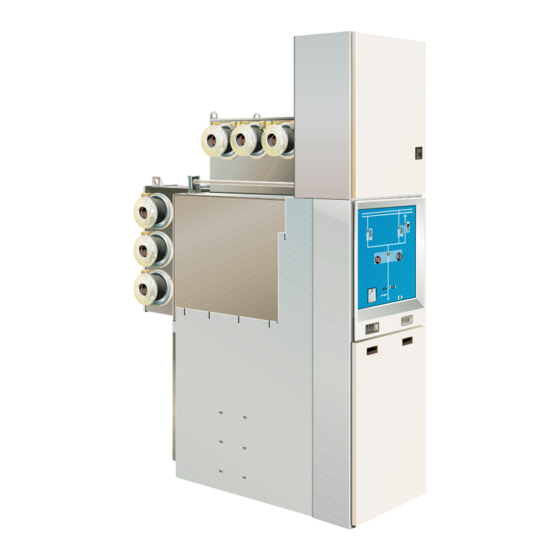
Page 7: Panel Description
Panel description Gas density switch of the IDIS systems for busbar 1 (rear busbar) Busbar link BB1 Circuit-breaker tank with vacuum interrupter chambers Outer cone-type cable connection Toroidal-core current transformer Voltage transformer (optional) Cable support Cable compartment cover Isolating device for voltage trans- former (optional) 10 Capacitive voltage detection system 11 IDIS display unit for monitoring of... - Page 8 Panel description Warning! Confusing the busbar system involves a risk of injury. The term Busbar 1 (BB1) refers to the busbar arranged in the rear area of the panel, and the term Busbar 2 (BB2) to the busbar arranged in the up- per part of the panel.
-
Page 9: Extension Of An Existing Double Busbar Switchgear System
extension of an existing double busbar switchgear system safety provisions Warning! Comply with the safety provisions on page 6. Warning! Confusing the busbar system involves a risk of injury. The term Busbar 1 (BB1) refers to the busbar arranged in the rear area of the panel, and the term Busbar 2 (BB2) to the busbar arranged in the up- per part of the panel. -
Page 10: Initial Situation
extension of an existing double busbar switchgear system Initial situation GHA double busbar switchgear panels can be extended at choice to the left or right sides. ● Both busbar systems are operating ● One busbar system alternately remains in operation during extension work. ●... -
Page 11: Extension On Left-Hand End Of Busbar
extension of an existing double busbar switchgear system extension on left-hand end of busbar Reroute all incoming and outgoing feeder panels to busbar 2 (Fig. 4). Isolate busbar 1 from the power supply and earth it (the diagram shows busbar earthing via the bus coupler, Fig. 4; see also Operating Manual, chap. - Page 12 extension of an existing double busbar switchgear system Treat all new contact surfaces in accordance with the Assembly Instruc- tions. Treat the new busbar clamping contacts for both busbar systems in accordance with the Assembly Instructions and insert them into the new panel (busbar tubes) to be lined up (Fig.
- Page 13 extension of an existing double busbar switchgear system The further steps for assembly are to be performed in accordance with the Assembly Instructions: – connect the earth bars – connect the low-voltage cables (ring lines, external customer cables) – Commission extension panels: –...
- Page 14 extension of an existing double busbar switchgear system On the new panels, mount all upper busbar links of the BB2 completely in accordance with the Assembly Instructions (Fig. 7). BB2 (top) BB1 (rear) Fig. 7 New panel connected to the two busbars Busbar 1 in operation Busbar 2 still earthed, but ready to operate (protective covers on busbar end not shown)
-
Page 15: Extension On Right-Hand End Of Busbar
extension of an existing double busbar switchgear system extension on right-hand end of busbar Reroute all incoming and outgoing feeders to busbar 1 (Fig. 8). Preparation SS 1 SS 2 BB2 (top) BB1 (rear) Fig. 8 All incoming and outgoing feeder panels on busbar 1, busbar 2 earthed via the bus coupler Isolate busbar 2 from the power supply and earth it (the diagram shows busbar earthing via the bus coupler, Fig. - Page 16 extension of an existing double busbar switchgear system Reroute all outgoing feeders to busbar 2 (Fig. 9). SS 1 SS 2 BB2 (top) BB1 (rear) Fig. 9 All incoming and outgoing feeder panels on busbar 2, busbar 1 earthed via the bus coupler Isolate busbar 1 from the power supply and earth it (the diagram shows busbar earthing via the bus coupler, Fig.
- Page 17 extension of an existing double busbar switchgear system 11. Position new panel on the base frame in accordance with the space as- Line up new panel signment plan, align it and screw-fasten it to the adjacent panel and the base frame (see Assembly Instructions). Mount busbar connection for busbar 1 completely with clamping contacts (see Assembly Instructions) (Fig.
- Page 18 extension of an existing double busbar switchgear system The further steps for assembly are to be performed in accordance with the Assembly Instructions: – connect the earth bars – connect the low-voltage cables (ring lines, external customer cables Commission extension panels: –...
- Page 19 extension of an existing double busbar switchgear system On the new panels, mount all upper busbar links of the BB2 completely in accordance with the Assembly Instructions (Fig. 12). BB2 (top) BB1 (rear) Fig. 12 New panel connected to the two busbars Busbar 1 in operation Busbar 2 still earthed, but ready to operate (protective covers on busbar end not shown)
-
Page 20: Replacement Of A Panel Within A Switchgear System
replacement of a panel within a switchgear system safety provisions Warning! Comply with the safety provisions on page 6 and 8. Warning! Confusing the busbar system involves a risk of injury. The term Busbar 1 (BB1) refers to the busbar arranged in the rear area of the panel, and the term Busbar 2 (BB2) to the busbar arranged in the up- per part of the panel. -
Page 21: Initial Situation
replacement of a panel within a switchgear system Initial situation ● both busbar systems are operating ● the incoming feeder panels are located at the appropriate end of the switchgear ● one busbar system continues to operate alternately during the replacement ●... -
Page 22: Fault In A Busbar Compartment
replacement of a panel within a switchgear system Fault in a busbar compartment In the following, a fault in the compartment of BB2 (upper busbar) of panel 7 (Fig. 14) is assumed. BB2 (top) BB1 (rear) Fig. 14 Illustrated: Fault on busbar 2 of panel 7 –... - Page 23 replacement of a panel within a switchgear system Earth busbar 2 on both sides of the panel concerned (7). To this effect, Removing the faulty panel earth busbar 2 additionally via the outgoing feeder of panel 8 (see Operat- ing Instructions) (Fig. 15). Attach a clear identification to busbars 1 and 2 of the adjacent panels.
- Page 24 replacement of a panel within a switchgear system Remove silicone sleeves of the busbar connections. Clean and grease the open busbar bushings on the adjacent panels and close them using surge-proof end caps (Fig. 16, item 1). Left-hand adjacent panel: narrow end caps Right-hand adjacent panel: high end caps Thus, both sections of busbar 2 are ready to operate.
- Page 25 replacement of a panel within a switchgear system Release the busbar connections ( BB1, rear busbar) in the faulty panel. Slip the clamping contacts into the busbar tubes of the left-hand panel (Fig. 19, item 2) and remove the silicone sleeves. Clean and grease the open busbar bushings on the adjacent panels and close them using surge-proof end caps (Fig.
- Page 26 replacement of a panel within a switchgear system BB2 (top) BB1 (rear) Fig. 20 Panel 7: Both busbars are disconnected. The busbars of the adjacent panels were closed by means of surge-proof end caps. Busbar 1 in operation, busbar 2 in operation. Surge-proof end caps Busbar clamping contacts Disconnect all the other panel connections:...
- Page 27 replacement of a panel within a switchgear system Fig. 21 Releasing the busbar link Clamping contacts Surge-proof busbar end caps Gha l switchgear extension and replacement of a panel...
- Page 28 replacement of a panel within a switchgear system Screw-fasten panels to adjacent panels and base frame (see Assembly Instructions). Earth BB1 sections. Warning! For safety reasons, all persons must be located in front of the switchgear during switching operations! Switch all outgoing feeder panels to BB2. After switching, open the disconnec- tors in the incoming feeder panels for BB1.
- Page 29 replacement of a panel within a switchgear system Re-establish all BB1 connections to the adjacent panels (6 x) completely (Fig. 23). Release the silicone sleeves and fasten them to the adjacent panel (see Assembly Instructions). BB2 (top) BB1 (rear) Fig. 23 Panel 7: busbar 1 with full continuity and ready to operate again, but still earthed.
- Page 30 replacement of a panel within a switchgear system The further steps for assembly are to be performed in accordance with the Assembly Instructions: – connect the earth bars. – connect the low-voltage cables (ring lines, external customer cables). Commission replacement panel: –...
- Page 31 Replacement of a panel within a switchgear system Earth BB2 on both sides of the panel concerned (shown in Fig. 25: busbar earthing through bus coupler and via outgoing feeder of panel 8, see also Operating Manual, Chapter 6.7). Warning! Risk of injuries.
- Page 32 replacement of a panel within a switchgear system On busbar 2 (top), remove the busbar end caps of the two adjacent pan- els. Clean and grease busbar bushings. Clean and grease silicone link sleeve, insert it under preload and mount it on the right-hand side of each panel.
-
Page 33: Annex
annex The required auxiliary equipment is described in the Assembly Instructions. In addition, the surge-proof end caps are required for panel replacement. Description Quantity Item no. flat end caps AGS 000 618-02 high end caps AGS 000 634-02 Assembly kit for end caps - special grease AGS 001983-01 - disposable gloves... - Page 34 Notes:...
- Page 36 AREVA T&D Worldwide Contact Centre http://www.areva-td.com/contactcentre/ ( +44 (0) 1785 250 070 www.areva-td.com...
Need help?
Do you have a question about the GHA series and is the answer not in the manual?
Questions and answers
How to add gas sf6