Advertisement
trevi showers.qxd
04/12/03 13:21
Page 1
TREVI SHOWERS
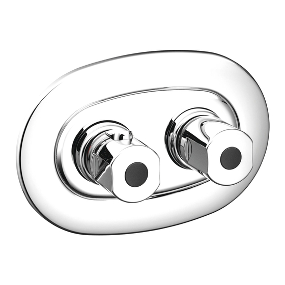
Trevi Outline
Trevi Traditional
Trevi Therm
Installation Instructions
A3000 Trevi Therm built-in thermostatic mixer
A3700 Trevi Outline built-in thermostatic mixer
E3115 Trevi Traditional built-in thermostatic mixer
INSTALLER:
After installation please pass this instruction booklet to user
Advertisement
Table of Contents


Need help?
Do you have a question about the Outline and is the answer not in the manual?
Questions and answers