Table of Contents
Advertisement
Advertisement
Table of Contents

Summary of Contents for olympia electronics BS-468
- Page 1 BURGLAR ALARM PANEL BS-468...
-
Page 2: Table Of Contents
Contents 1. Description ............................3 2. Instructions for the user ........................4 2.1Basic operations ..........................4 Complete system.............................. 4 Split system..............................4 2.2 Armed system indication ....................... 5 2.3 Advanced operations ........................5 2.4 Main User menu ..........................7 3. -
Page 3: Description
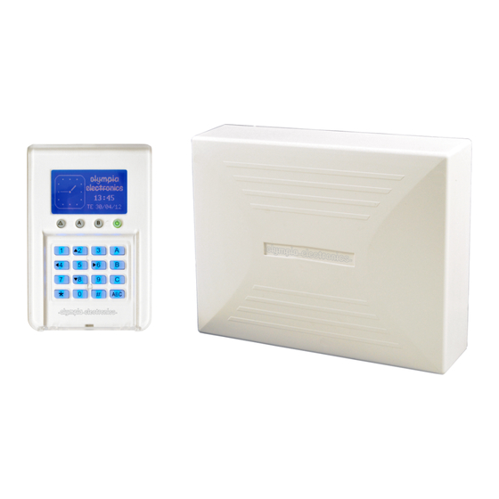
1. Description The BS-468 is an 8 zone burglar alarm panel. Using the special expansion card BS-469 it can be expanded to 16 zones. For its operation, at least one BS-466 keyboard is required. Up-to 8 keyboards can be connected to the panel. Each keyboard has an additional zone for connecting magnetic contacts (zones 17–24). -
Page 4: Instructions For The User
2. Instructions for the user 2.1Basic operations The panel has 1 main code (master) which by default is set to [1 2 3 4] and up-to 50 user codes which by default are not programmed. The system can operate with two different modes. Depending on the mode of operation, the arm and disarm operations differ. -
Page 5: Armed System Indication
2.2 Armed system indication When the system is armed then next to the clock, instead of the Olympia electronics logo there is a lock symbol. Next to the lock symbol we can see which sections are armed. In this example we can see that the system is partially armed because only the C section is armed. - Page 6 (If a GSM is connected) PANEL SOFT VERSION TECHNICIAN INFO The selection «TECHNICIAN INFO» by default has information of SIGNAL LEVEL Olympia electronics. 11-4-2017 921468001_09_015...
-
Page 7: Main User Menu
If “SIGNAL LEVEL” is selected and a GSM module is not connected NO GSM CONNECTED then the following message is shown. PRESS ‘#’ TO RETURN 2.4 Main User menu Via the user menu we can change critical parameters of the system. To enter the user menu we must know the master code. - Page 8 We enter the number of the password (i.e. 03) which we want to change and we see: 03:CHANGE PASSWORD - - - - After entering the 4 new digits the system request us to repeat them. We enter again the 4 digits. If the codes match then the change is made and the display shows the relative message.
- Page 9 With the selection «CHANGE DAY OF WEEK» we see: _ CHANGE DAY OF WEEK _ MONDAY With the up and down cursor key we select the required day and TUESDAY by using the (*) key we make the selection. WEDNESDAY THURSDAY FRIDAY SATURDAY...
- Page 10 Finally the MASTER MENU has the option «TIMERS». With this selection we can program up to 10 automatic arming or disarming procedures of all or part of the system. Selecting «TIMERS» we see the display below. If the «CHANGE TIMER» is selected then this means that the timer is active. If the «DELETE TIMER»...
- Page 11 By pressing the (*) key we see: We make the required selection of the function that we want the _ CHANGE ACTION _ timer to do and press the key (*). The system confirms the ARM ALL selection. DISARM ALL The event memory logs the arming or disarming of the system but ARM Α...
-
Page 12: Installation Instructions
3. Installation instructions 3.1. Quick installation guide By default the panel has the following settings section Α Zone 1 : Zone with delay section Β Zone 2 : Zone with delay Ζone 3 : Zone without delay section Β Ζone 4 : Zone without delay section Β... - Page 13 All zones are on the same section and the system arms and disarms all together. On zone 1 the magnetic trap activated the bell on the keyboard to warn us that the door has opened. section Α 2. Zone 1 : Zone with delay section Β...
- Page 14 This program is identical to the previous program but with more zones for the store. section Α Zone 1 : Zone with delay section Α Zone 2 : Zone with delay section Α Zone 3 : Zone without delay section Α Zone 4 : Zone without delay section Α...
-
Page 15: Connections
3.2. Connections Connecting the battery and the mains power supply For the battery there are two cables, red and black for connecting to the positive and negative pole respectively. Keyboard connections To facilitate the installation, the keyboard has two parts, the base and the main body. The base is the part that must be mounted to the wall. -
Page 16: Siren Connections
Connecting 8 keyboards to the panel. The cables must be connected in such a way that will permit the connection of the device one after the other. No terminal should contain 3 cables or more. The jumpers of the terminal resistors must be placed only on the two outer most devices. On all the other devices is should be removed or left in a open position. - Page 17 For connecting the autonomous siren type BS-413 up-to 7 cables are required. On the terminals (+) και (-) connect the voltage (AS), (-) which charges the siren. When we supply the (ST) with 12V the siren and the beacon are activated. It is connected to the P1 contact of the panel which is programmed to provide 12V during an alarm and 0V during the idle state.
-
Page 18: Zone Connections
Zone connections Connecting the panel with radars (infrared movement detectors, PIR) or other devices which require power. For the connection, 4 cables are required (6 if the TAMPER is connected). The 2 cables are connected to the (12V) and (-) of the panel and provide power to the respective terminals of all the detectors. -
Page 19: Smoke And Heat Detector Connections
Smoke and heat detector connections The connection of the fire detectors must be done to a zone which has been programmed as a «FIRE» zone. The normally closed contacts of the relay on the base (NC,C) are connected in series with the resistor of the zone of the panel. -
Page 20: Programming Via The Keyboard
3.3. Programming via the keyboard Let it be noted that when trying to change a setting in the user menu or the technician menu you can view the current value of the setting. The only menus that do not offer the preview of default values are the 2 menus «CALL ON»... -
Page 21: Programming How The Passwords Function
By entering the technician’s password we enter the technician menu and we see: __ TECHNICIAN MENU __ EVENTS By selecting the «EVENTS» option we can erase the events log. If CODES we make this selection the system asks for a confirmation and then erases the entire events log. -
Page 22: General Settings
SILENT ALARM. The code activates the silent alarm. When the user enters the code, the panel will disarm (if the panel is armed) and will remain in idle state (the siren will not sound, and the alarm leds will be off). The panel will call or send a message via BS-465 or BS-464 to the selected telephone numbers. -
Page 23: Automatic Arming-Disarming
«AUTOMATIC BYPASS» By selecting YES, all zones that have be programmed with bypass capabilities (see zone programming), if during the arming are active (i.e. an open window) are bypassed automatically by the system. When the zones are deactivated (i.e. the window has closed) they are automatically activated. -
Page 24: Zone Programming
We enter the hours and minutes that we want the timer to activate and we see: _ CHANGE DAY OF WEEK _ EVERY DAY We select the day of the week when we want the timer to activate. If we select «EVERY DAY» the timer will activate all of the days. MONDAY TUESDAY WEDNESDAY... - Page 25 «ZONE WITH DELAY». The zone will issue an alarm after an entrance delay. This selection is used for the magnetic contacts that are used for the main entrance and also for the radar the will detect the user before he reaches the panel to disarm it. «"ZONE WITHOUT DELAY».
-
Page 26: Output Programming
zone. The zone is regarded again by the system when it stops being active ( i.e. when the window closes). If we select NO and the zone during the arming process is active (i.e. open window) and the automatic bypass has been selected, the system will warn us that the arming is not possible. For the last three setting if we select ZONE MODE the panel will automatically select the correct setting. -
Page 27: Programming The Pstn Bs-465 Telephone Dialer
ALARM AND FAULT display. More option can be viewed only with the computer software ALARM ONLY PC-468 that accompanies the panel BS-468. FAULT ONLY PANIC AND FIRE ONLY Due to the fact that in this menu not all option are shown, the cursor TAMPER ONLY does not highlight the current option but always the top most. -
Page 28: Programming The Gsm Bs-464 Telephone Dialer
After making the required selection it is time to enter the actual telephone number. Due to the fact that the ‘*’ and or ‘#’ can be part of the number, the LINE NUMBER ENTRY storage is done using the ‘Α’ key, the cancellation is done using ‘Β’ 6977123456----------- key and finally with the ‘C’... - Page 29 ALL EVENTS can be viewed only with the computer software PC-468 that accompanies ALARM ONLY the panel BS-468. FAULT ONLY PANIC AND FIRE ONLY Due to the fact that in this menu not all option are shown, the cursor does ON ARM not highlight the current option but always the top most.
- Page 30 PIN number. Remove the card from the phone and replace it in the socket of the GSM card. Reinstall the GSM card on the panel BS-468. Please note that the PIN code is requested twice. For the code to be ---- considered correct we must enter it correctly both times.
-
Page 31: Resetting To Factory Default Passwords
3.4. Resetting to factory default passwords The main board of the panel contain 2 pins with the marking CODE RESET. With this we can reset the passwords to the factory defaults by following the procedure below: 1. Connect the cable SERVICE of the siren to a (-) on the panel. 2. -
Page 32: Programming From The Computer
The programming of the panel can be done easily by using the special computer software PC-468 that is provided free by Olympia Electronics. To connect the panel to the computer a simple mini-USB cable is required. This is provided with the BS-468/KEYPAD as well as the newest version of the software. -
Page 33: Connection Function
Connection function To establish a connection with the panel, connect the usb cable to the keyboard BS-466 and click on as shown in the screen above. The indicators on the bottom left corner must be green. After the connection is established the panel settings are shown. (below screen) Next the connected devices and the keyboards are shown. - Page 34 We can receive all the settings of the panel by clicking on , as shown below. The panel requests a password for this operation. We must enter either the technician code ( 9 9 9 9 ) or the main user password ( 1 2 3 4 ) to receive all the settings of the panel. Next we can set or view all the settings of the panel such as zones, passwords, events, timers and outputs.
-
Page 35: Programming The Panel
Programming the panel We can view or alter the settings of the panel. The above settings can be altered only be using the keyboard but by using the software we have a better visual perspective and the programming is easier. Also by using the software we can easily synchronize the date and the time of the computer to that of the panel by clicking on the corresponding button. - Page 36 If for example we want to change the entrance time to 10 seconds press the up arrow next to the 7 second entrance time as shown below. We see that the entrance time 10 is highlighted. This means that we have changed this setting but the have not been stored yet. By clicking on the button «Send» a window is shown for sending the new settings to the panel.
-
Page 37: Zone Settings
Zone settings To set the zones of the panel we select the option «Zones». And a screen like the one below is shown. The technician can alter the operation of each zone whereas the main user can give a name to each zone so it can be easily recognized. -
Page 38: Password Settings
Password settings If the technician enters the password option he can change only the reaction, section and output as shown in the screen below. The technician can also make changes to the codes which can also be done from the BS-466 keyboard. - Page 39 When we enter a code it request for us to enter it 2 times in order to avoid errors. In the previous screen we a can see an option «Visible codes». With this option the main user can later if the codes will be shown or if they will be in the form an asterix. The screen above shows a typical system.
-
Page 40: Events
Events We this option we can see all the events of the panel. Clicking the button «Receive» to view all the events that have occurred The columns shown are: Α/Α the number of the event Date and time of the event. Category. -
Page 41: Timer Settings
Warning!! The events of the panel are not stored with the settings of the panel. If we want to have the events of the panel we can store them in a separate file by clicking the button «Save» on the lower right side as shown on the screen below. With the button «Open»... -
Page 42: Output Settings
The screen above shows timer 2 used to disarm section A every Wednesday at 7:00 AM whereas timer4 arms the system every Wednesday at 7:00 PM. Output settings The option OUTPUTS is used to show all the outputs. The function is as described in altering the outputs by the BS-466 keyboard. -
Page 43: New File
New file With this option we can start a new installation without the panel being connected. First we select what the panel will contain e.g. GSM, keyboards 1,2,5 and 6. Next we alter all the required settings and save the file using the selection File Save. Open file When we select to open a file, a window in shown like in the screen below. -
Page 44: I - Olympia Application
Then we can do a transfer of the settings to the panel as shown in the screen above. I - OLYMPIA APPLICATION “Olympia Electronics Alarm” application is available for smart phones and tablets for Android or IOS. You can download it at Google play or Apple store. -
Page 45: Technical Characteristics
4. Technical Characteristics Description BS-468 Burglar alarm system Power Supply 220-240V AC/50-60Hz Consumption 25VA Battery type Sealed lead acid (Pb) battery 12V / 7Ah Max (not included) Charger Stabilized power supply 13,8V / 400mA AS siren circuit The AS output powers the external sirens and is used to charge the battery of the siren with a rating of 13,8V 500mA. -
Page 46: Peripheral Device Consumption Chart
Olympia Electronics reserves the right to repair or to replace the returned goods and to or not charge the buyer depending on the reason of defection. Olympia Electronics reserves the right to charge or not the buyer the transportation cost. -
Page 47: Information Regarding The Installation
4.2. Information regarding the installation Passwords Master password: (1 2 3 4 ) ____________ Α/Α Α/Α Password Owner Function Password Owner Function Zones Section Section Section Α/Α (Α Β C) Α/Α (Α Β C) Α/Α (Α Β C) Area Area Area Various information Entry time : ________ seconds Exit time : _________ seconds...
Need help?
Do you have a question about the BS-468 and is the answer not in the manual?
Questions and answers