Sign In
Upload
Download
Table of Contents
Contents
Add to my manuals
Delete from my manuals
Share
URL of this page:
HTML Link:
Bookmark this page
Add
Manual will be automatically added to "My Manuals"
Print this page
×
Bookmark added
×
Added to my manuals
Manuals
Brands
Tremec Manuals
Other
TR-3550
Service manual
Tremec TR-3550 Service Manual
Hide thumbs
1
2
Table Of Contents
3
4
5
6
7
8
9
10
11
12
13
14
15
16
17
18
19
20
21
22
23
24
25
26
27
28
29
30
31
32
33
34
35
36
37
38
39
40
41
42
43
44
45
46
47
48
49
50
51
52
page
of
52
Go
/
52
Contents
Table of Contents
Bookmarks
Table of Contents
Table of Contents
Important Notice-Before You Begin Service
Identify Your Type of Tremec Tr·3550 or Tremec Tko Transmission
Shifter Location Conversion Kits
Disassembled View Legend - Late Design and TKO
Disassembled View
Dissassembled View Legend
To Repl Ace T-5 Transmission with Tremec TR-3550 or TKO High Performance Transmissions
Transmission Removal
Transmission Installation
Disassembly - Transmission
Input Shaft Bearing
Countershaft (Cluster Gear) - Early One-Piece Design
Countershaft (Cluster Gear) - Late Th Ree-Piece Design
Disassembly and Assembly-Subassemblies
Fifth Gear Synchronizer Assembly
Reverse I Dler Assembly- Early and Late Designs
Output Shaft and Gear Assembly - Early and Late Designs
Synchronizer
Case Cover and Shifting Mechanism
Shifting Lugs
Extension Housing
Reverse Inhibitor Assembly
Extension Housing Rear Seal
Assembly - Transmission
Transmission Diagnosis
Transmission Cleaning
Inspection
Specifications
Introduction
Nomenclature for Bolts
Bolt Strength Identification
Hex Nut Strength Identification
English/Metric Conversion
Decimal and Metric Equivalents
Torque Conversion
Advertisement
Quick Links
1
Identify Your Type of Tremec Tr·3550 or Tremec Tko Transmission
2
Disassembled View Legend - Late Design and Tko
3
Specifications
Download this manual
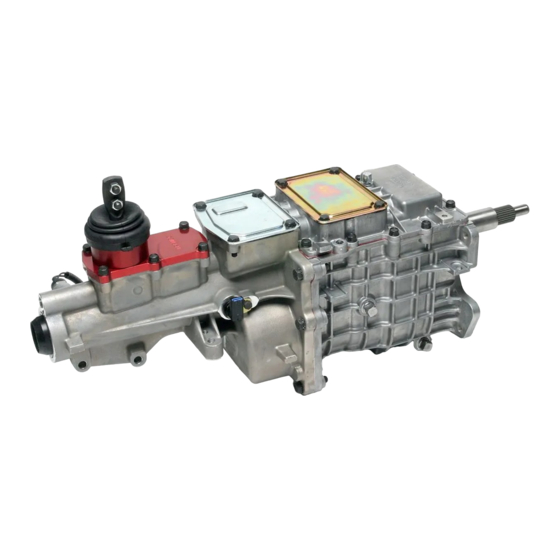
TR-3550 I TKO
SERVICE MANUAl
BULLETIN NUMBER
TRSM-TK0-0711
Table of
Contents
Previous
Page
Next
Page
1
2
3
4
5
Advertisement
Table of Contents
Need help?
Do you have a question about the TR-3550 and is the answer not in the manual?
Ask a question
Questions and answers
Related Manuals for Tremec TR-3550
Tremec TKO Service Manual
(52 pages)
This manual is also suitable for:
Tko
Table of Contents
Save PDF
Print
Rename the bookmark
Delete bookmark?
Delete from my manuals?
Login
Sign In
OR
Sign in with Facebook
Sign in with Google
Upload manual
Upload from disk
Upload from URL


Need help?
Do you have a question about the TR-3550 and is the answer not in the manual?
Questions and answers