Table of Contents
Advertisement
Quick Links
Advertisement
Table of Contents

Related Manuals for Brolight BIM-7001

Summary of Contents for Brolight BIM-7001
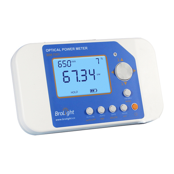
- Page 1 OPTICAL POWER METER 光功率计 User Manual...
- Page 2 OPTICAL POWER METER USER MANUAL Hangzhou Brolight Technology Co., Ltd. 版权所有:杭州博源光电科技有限公司 Ver. 版本: Date 日期: 2018,9,25...
-
Page 3: Table Of Contents
Contents 1. Introduction ................................- 2 - 2 Unpacking & checklist .............................. - 3 - 3. Features and Specifications ............................- 4 - 3.1 Features ................................- 4 - 3.2 Specifications ..............................- 4 - 4. Operation guide ................................ - 5 - 4.1 Power Adapter .............................. -
Page 4: Introduction
1. Introduction This manual suitable to below optical power meter model: 1111 BIM-7001 optical power meter Thank you for purchasing hank you for purchasing the high performance optical power meter, featuring a large High-speed HD display. The range of wavelength and power in the measurement is determined by the detector. -
Page 5: Unpacking & Checklist
DOCID#: CD-M-BIM-7001D U S E R M A N U A L Chapter 2 2 Unpacking & checklist Please note the Arrow direction of the box. Always face the Arrow point upwards before o pening the box. Please check if there is any missing item according to the checklist. In case of you find any damage or shortage , Pls contact us immediately. -
Page 6: Features And Specifications
Multi wavelengths measurement Data stored and read, Out-range alert Power Management Function Alarm over range PC software real-time display power value Specifications Name BIM-7001 Compatible Detectors BIM-71 series detertors,BIM-72 series detertors Spectral Range 0.19um-25um Power Display Range 1pW-20kW... -
Page 7: Rechargeable Battery
DOCID#: CD-M-BIM-7001D U S E R M A N U A L Chapter 4 4. Operation guide 4.1 Power Adapter 4.1.1 Power Adapter In order to make sure this device work well, it is highly recommended that only use the power adapter, which we shipped together with power meter. -
Page 8: Front Panel
Auto Power -Off Form 4-1 Display information of BIM-7001 These listed icons you may meet when you use BIM-7001. Each icon represent a real function. After installing the rechargeable batteries, there will be show on the screen. It shows the battery level indication. -
Page 9: Front Panel Keys
DOCID#: CD-M-BIM-7001D U S E R M A N U A L 4.2.2 Front Panel keys Figure 4-2 The front panel buttons Power supply Short press (shorter than 2s. Unless point out specifically, short press means press shorter than 2s) the power button starting up. - Page 10 DOCID#: CD-M-BIM-7001D U S E R M A N U A L ④ In setting lower limits mode, long pressing this button will enter setting upper limits mode. Press button 9and 10 to set the upper limits value which displays in the middle of the LCD. When the measure value more than it, alarming will occur, It will return to Absolute power measurement mode without any operation in 10s.
- Page 11 DOCID#: CD-M-BIM-7001D U S E R M A N U A L (2)When using with Attenuator, long pressing this key will show “ATT” on the screen. It means Attenuator has been opened. When the detector is not connected with the Attenuator, long press will cause “nA”on the screen, and it means “no Attenuator”.
-
Page 12: The Default Settings
DOCID#: CD-M-BIM-7001D U S E R M A N U A L Button right (1)In setting up/low limits of the power mode, short press this key can increase the power value, and long press it can quickly increase the power value. In Reading memory data mode, short press this key can read the next data that the memorizer has stored. -
Page 13: Connector Description
DOCID#: CD-M-BIM-7001D U S E R M A N U A L Form 4-3 Signals 4.2.5 Connector description Figure 4-3 Connector (1) External Power Supply Connector: +6VDC. (2) DB15: Connector to the detector. (3) USB: Communication with PC. (4) Insert the rechargeable battery. - 11 -... -
Page 14: System Operation
DOCID#: CD-M-BIM-7001D U S E R M A N U A L Chapter 5 5 System operation 5.1 Connection and Setup Connect the detector to the DB15 connector on the flank panel of the optical power meter. The optional external power supply of the power meter is including rechargeable battery and power adapter. -
Page 15: Setting The Attenuator Mode
DOCID#: CD-M-BIM-7001D U S E R M A N U A L 5.4 Setting the Attenuator Mode If the light intensity more than the detector’s Saturation value, you have to order the attenuator to get the right data. In the attenuator mode: a) ATT signal indication b) The response of detector - attenuator will be used in the process of verification Please long press the “ATT”... -
Page 16: Relative Measurment(Db
DOCID#: CD-M-BIM-7001D U S E R M A N U A L 5.6.2 Relative measurment(dB) The dB measurement mode displays the absolute value of 10 times the logarithm (base 10) of the input power, referenced to a power level which is selected by pressing the REF key. The following equation illustrates this relationship: dB reading=10*lg[Net Applied Power/Net Referenced Power] =10*lg{[(P-P... -
Page 17: Shutdown
DOCID#: CD-M-BIM-7001D U S E R M A N U A L 5.9 Shutdown Long pressing the , when the auto- shutdown function is open, if there is not any operation in 10mins, it will Auto Power -Off . After startup, press the Power Button last more than 1 second again, the power meter will be shutdown. -
Page 18: Maintenance And Storage
DOCID#: CD-M-BIM-7001D U S E R M A N U A L Chapter 6 6. Maintenance and storage In order to ensure the equipment performance and life span, Please use it in temperature 15℃ ‐30℃ and relative humidity 5%‐85% RH. ...
Need help?
Do you have a question about the BIM-7001 and is the answer not in the manual?
Questions and answers