
Summary of Contents for SnowEx V-Maxx G2 VX-2200
- Page 1 October 15, 2017 Lit. No. 70455, Rev. 04 V-Maxx™ G2 Hopper Spreader VX-2200 / VX-2200HO Installation Instructions CAUTION Read this document before installing or operating the spreader. A DIVISION OF DOUGLAS DYNAMICS, LLC...
-
Page 2: Safety Definitions
SAFETY SAFETY DEFINITIONS WARNING/CAUTION LABELS Become familiar with the warning and caution labels WARNING on the spreader. Indicates a potentially hazardous situation that, if not avoided, could result in death or NOTE: If labels are missing or cannot be read, see serious personal injury. -
Page 3: Serial Number Label
SAFETY ROTATING AUGER CAN CAUSE SERIOUS INJURY OR DEATH • Keep arms, hands, and loose clothing away from auger. • Shut off control and unplug spreader before servicing. D6335 Serial Number Label (inside frame) SERIAL NUMBER LABEL Code Defi nition 2-Digit Year 2-Digit Month 2-Digit Day... -
Page 4: Safety Precautions
SAFETY SAFETY PRECAUTIONS CAUTION • Do not operate a spreader in need of Improper installation and operation could cause maintenance. personal injury and/or equipment and property damage. • Before operating the spreader, reassemble Read and understand labels and the Owner's Manual any parts or hardware removed for cleaning before installing, operating, or making adjustments. - Page 5 SAFETY PERSONAL SAFETY VENTILATION WARNING • Remove ignition key and put the vehicle in park or in gear to prevent others from starting the vehicle Vehicle exhaust contains lethal fumes. during installation or service. Breathing these fumes, even in low concentrations, can cause death.
-
Page 6: Torque Chart
SAFETY TORQUE CHART CAUTION Read instructions before assembling. Fasteners should be fi nger tight until instructed to tighten according to torque chart. Use standard methods and practices when attaching spreader, including proper personal protective safety equipment. Recommended Fastener Torque Chart Inch Fasteners Grade 5 and Grade 8 Torque (ft-lb) Torque (ft-lb) -
Page 7: Material Weights
LOADING MATERIAL WEIGHTS These installation instructions cover vehicles that have been recommended for carrying the hopper spreader. Please see your local dealer for proper vehicle Density applications. Material (lb/ft (lb/yd (kg/m Salt 2160 1282 CERTIFICATION Sand 2700 1602 WARNING Material densities are approximate and are based on dry, loose material. -
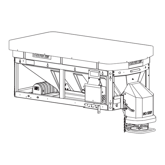
Page 8: Mounting The Spreader
MOUNTING THE SPREADER INSTALL HOPPER IN VEHICLE BED NOTE: Periodically throughout the snow and ice control season, verify that mounting devices 1. Remove the vehicle tailgate. are secure. CAUTION Remove the pallet, top screen, parts boxes, and Before lifting, verify that the hopper is empty spinner assembly. - Page 9 MOUNTING THE SPREADER INSTALL SPINNER ASSEMBLY TO 3. Connect the spinner motor plug to the spinner harness plug on the rear of the electrical control HOPPER box. 1. Move the spinner assembly upward into position and set the support tabs on top of the rear frame. IMPORTANT: When installing the spinner assembly on the spreader, make sure the material chute fi...
-
Page 10: Install Mounting Hardware
MOUNTING THE SPREADER 3. Using the mounting holes in the spreader side INSTALL MOUNTING HARDWARE rails as a template, mark mounting hole positions on the vehicle bed. Drill 9/16" holes for the frame 1. Position the spreader so the material chute on the bolts. - Page 11 MOUNTING THE SPREADER Construct Sill Spacer Install Tie-Down Ratchet Straps Measure the distance from the front end of the hopper Install ratchet straps from the large round holes on the sill to the front of the vehicle bed and make a spacer top of the diagonal corner rails of the spreader frame from 2"...
-
Page 12: Wiring Instructions
WIRING AND HARNESS INSTRUCTIONS WIRING INSTRUCTIONS Vehicle Battery Cable Installation Spreaders are shipped from the factory with the 1. Before beginning this installation, remove the spreader harness wired to the motor and spreader battery cables from the vehicle battery. module. 2. - Page 13 WIRING AND HARNESS INSTRUCTIONS Vehicle Control Harness Installation 5. Insert a rubber grommet into the hole. 6. Route the harness as laid out in Step 2. 1. Plug the vehicle harness into the spreader harness. Secure the vehicle control harness to the vehicle. 2.
- Page 14 WIRING AND HARNESS INSTRUCTIONS CENTER HIGH-MOUNTED STOPLIGHT 4. Install the control side of the bracket to the vehicle side using 1/4" x 1/2" Phillips head machine (CHMSL) screws, 1/4" shoulder washers, 1/4" lock washers, and 1/4" locknuts. An LED center high-mounted stoplight is standard equipment on all V-Maxx™...
-
Page 15: Electrical Components
ELECTRICAL COMPONENTS VEHICLE HARNESS DIAGRAM Cab Control 18 ga Red 4-Way Connector To Vehicle Switched Accessory Vehicle Control Harness To Vehicle CHMSL Signal (tap located in cab) Connectors 18 ga Shielded Twisted-Pair Cable 6 ga Red 100 A Fuse 4 ga Red 18 ga Black Vehicle 4 ga Black... - Page 16 ELECTRICAL COMPONENTS ELECTRICAL CONTROL BOX SCHEMATIC ACC Relay-Fuse Spreader Module Mounting Bracket SPIN FEED Feed Feed (Auger Drive) (Auger Drive) Switch Switch Accessory Work Light Switch To CHMSL To Auger Motor Spreader Harness Vibrator Assembly Harness ACC Power Block ACC Taps (cover removed) To Spinner Motor...
-
Page 17: Final Adjustments
FINAL ADJUSTMENTS FINAL CHECKLIST Verify that the auger and spinner turn freely. Verify that dielectric grease is applied to all electrical connections. Verify that wire harnesses and battery cables are properly secured away from hot or moving parts. ... - Page 18 Do not exceed vehicle ratings with a spreader. TrynEx International offers a limited warranty for all spreaders and accessories. See separately printed page for this important information. The following are registered ( ® ) or unregistered (™) trademarks of Douglas Dynamics, LLC: SnowEx , V-Maxx™. ® Printed in U.S.A.
Need help?
Do you have a question about the V-Maxx G2 VX-2200 and is the answer not in the manual?
Questions and answers